(
Attach a tachometer according
to
its
manufacture
's
instructions.
Read the
instruction
for
timing
light
operation.
Start the engine and
hold it at 1,800 ± 100
rpm
while
pointing
the
timing
light
towards
the
index
notch.
The
ignition
timing
is correct
if
the "F"
mark
on the
flywheel
aligns
with
the index notch in the left
crankcase
cover
.
Check
that
the
O-ring is in good
condition,
replace it
if
necessary.
Apply
oil to the O-ring and install it
onto
the
timing
hole cap.
App
ly grease
to
the
timing
hole cap threads.
Install
the
timing
hole cap and
tighten
it
to
the spec-
ified torque.
TORQUE:
10 N'm 11.0
kg
f·m. 7 Ibf·
ftl
THROTTLE POSITION SENSOR
INSPECTION
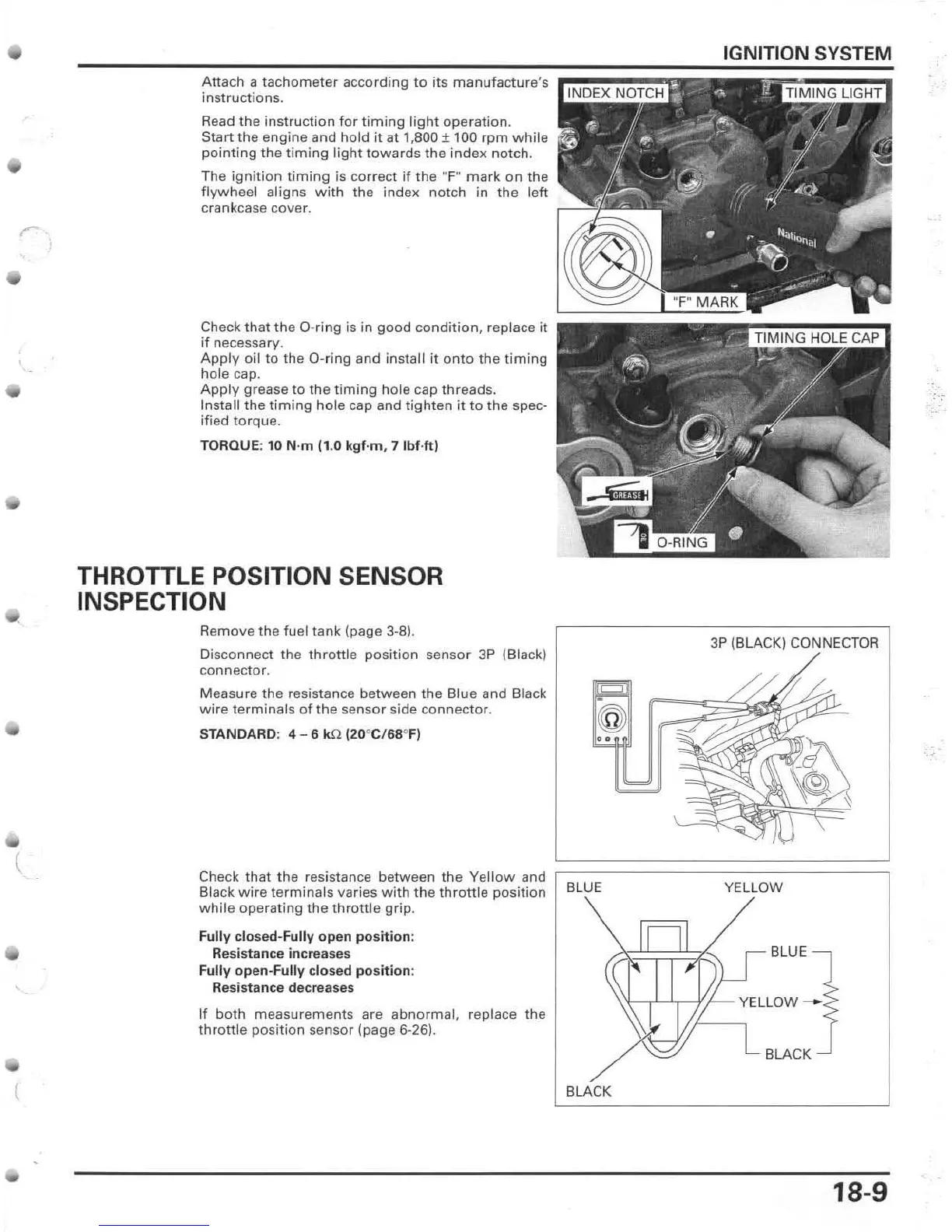
Remove the fuel tank (page 3-8).
Disconnect the
throttle
pOSition sensor 3P (Black)
connector.
Measure
the
resistance between the Blue and Black
wire
terminals
of
the sensor side connector.
Check that the resistance between
the
Yellow
and
Black
wire
terminals
varies
with
the
throttle
position
while
operating
the
throttle
grip.
Fully closed-Fully open pos
iti
on:
IGNITION SYSTEM
3P (BLACK) CONNECTOR
••
BLUE YELLOW
Resistance
incr
eases BLUE
Fully open-Fully clo
se
d pos
iti
on:
Resistance decreases
If both measurements are
abnormal,
replace the
throttle position sensor (page 6-26).
BLACK
BLACK
18-9
,.-
 Loading...