MAINTENANCE
3-6
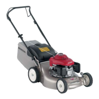
Insert a feeler gauge [1] between the tappet adjusting
screw [2] and valve stem [3] to measure the valve
clearance.
If adjustment is necessary, proceed as follows.
ADJUSTMENT
Hold the tappet adjusting screw using the special tool
and loosen the lock nut [4].
Turn the adjusting screw to obtain the specified
clearance.
Hold the adjusting screw and tighten the lock nut to the
specified torque.
Recheck the valve clearance, and if necessary, readjust
the clearance.
Installation is in the reverse order of removal.
• Apply liquid sealant to the cylinder head cover
mating surface (page 10-5).
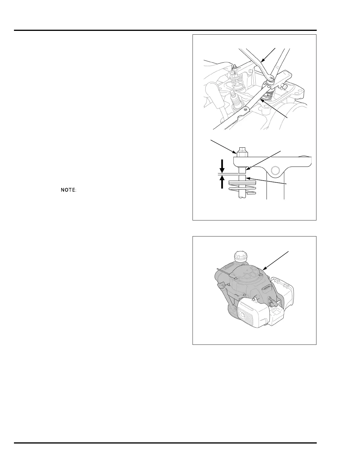
RECOIL AIR INLET CLEANING
Remove the top cover (page 5-2).
Clean dirt and grass from around the inside [1] of the
top cover.
VALVE CLEARANCE:
IN/EX: 0.10 ± 0.02 mm (0.004 ± 0.001 in)
TOOL:
Valve adjusting wrench [5] 07908-KE90000
TORQUE: 8 N·m (0.8 kgf·m, 5.9 lbf·ft)
[5]
[2]
[1]
To increase valve clearance; screw out
To decrease valve clearance; screw in
[3]
[4]
 Loading...