12-16
VARIABLE MOWING SYSTEM/ MOWER DECK/WHEELS HRN216
8. Remove the discharge guard by driving out the metal
shaft from one side.
The discharge guard springs are under heavy tension
and can fly out and injure you. Apply downward
pressure with a gloved hand to each spring as you
remove the shaft to maintain control of the springs.
9. Remove the rear shield (P. 1 2 - 17
).
INSTALLATION
Installation is the reverse order of removal.
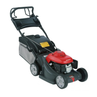
• Check that the two Roto-Stop cover tabs are fully inserted
into the retaining slots in the rear housing assembly
(P. 12-4
).
VKA/VLA/VYA types:
• Make sure the drive belt is installed on the correct side of
the rib guide as shown.
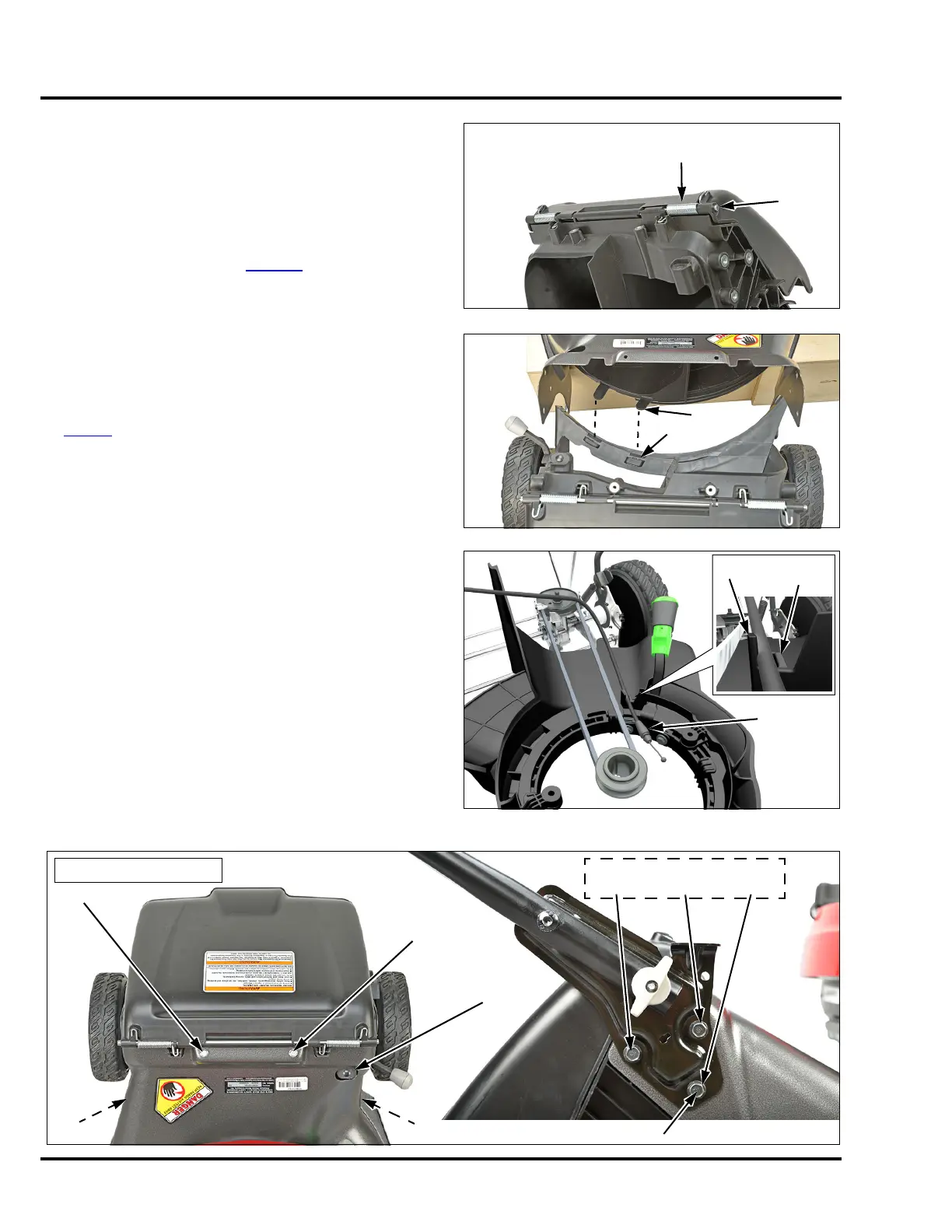
• The 10 bolts that fasten the rear housing to the mower
deck and handle stays MUST be tightened in the
following sequence shown below:
a. The threaded nut inserts that attach the handle stays
should be centered and visible through the holes in
the metal mower deck and then hand start each of
the 10 bolts in the numbered sequence below.
b. Place the mower on all four wheels and then fully
tighten the 10 bolts in the same numbered sequence
to the specified torque below.
• Be sure the Smart Drive cable holder exits through the
mower deck and is not pinched or offset.
SHAFT
Apply downward
pressure to the
springs.
RIB
Do not install
belt in this
area.
ROTO-STOP
CABLE (VYA)
6 mm FLANGE BOLT (4)
SMART DRIVE
CABLE HOLDER
TORQUE: 11 N•m (8.1 ft-lb)
Same sequence on both sides
 Loading...