EasyManua.ls Logo

Honeywell Apex User Manual

Honeywell Apex
128 pages
To Next Page IconTo Next Page
To Previous Page IconTo Previous Page
Page #115 background image
115
MAN0604_Issue 09_02-2013 Apex
2110M8030
APPENDIX A - SPECIFICATIONS
54 27 Calibration Required
62 31 Transmitter Alarm Setting Failure
64 32 Sensor Comms Failed
102 51 FatalFault
202 101 TransmitterFailed
204 102 TransmitterFailed
226 113 Transmitter Failed
A.4.3 Sensor Object
The sensor object has one network variable input and eleven network variable outputs.
nviResetAlm input
This network variable causes latching alarms and faults to be reset. The reset will only take place if
thecauseofthefaultoralarmnolongerexists.Additionally,theresetonlyoccurswhenanon-zero
update is sent to this input.
This means that sending an ST_LOW to this input once will not have any effect on alarms or faults
that occur later. This input resets both the local relays and LonWorks network variables.
nvoAlmL output
This network variable normally has the value ST_OFF. When a level 1 alarm exists the alarm1 relay
will be activated and this output will have the value ST_LOW.
When a level 2 alarm exists the alarm2 relay will be activated and this will produce ST_MED.
nvoAlm2 output
This variable normally has the value ST_OFF. When a level 2 alarm exists this will have the value
ST_MED.
This network variable is provide for use with common shutdown relays that are not capable of
discriminating between ST_LOW and ST_MED in installations where discrimination between alarm1
and alarm2 is desired.
nvoAlarmThresh1 and nvoAlarmThresh2 outputs
These network variables indicate the current alarm thresholds of this instrument. Gas concentrations
greater than the amount reported in these variables will cause the alarms to activate. See the related
subsequent discussion of nviHighLim1 and nviHighLim2.
The units are the same as the front panel display and will be indicated by nvoConcType, below. The
units will be ppm, %LEL and %V/V respectively when gas sensor cartridges for toxic, explosive and
oxygen gasses are installed.
For example if an H
2
cartridge is installed and nvoAlarmThresh1 is 50.00, this means that alarm1 will
activate when the H
2
concentrations exceeds 20,000 ppm since LEL for H
2
is 40,000 ppm.

Table of Contents

Question and Answer IconNeed help?

Do you have a question about the Honeywell Apex and is the answer not in the manual?
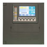
Honeywell Apex Specifications

General IconGeneral
TypeAddressable Fire Alarm Control Panel
Power Supply120/240 VAC, 50/60 Hz
Operating Temperature32°F to 120°F (0°C to 49°C)
Humidity Range10% to 93% non-condensing
CompatibilityHoneywell Notifier devices and compatible peripherals
CertificationsUL, FM, CSFM

Summary

Safety Information

General Safety Warnings

Critical safety advice applicable before installation or operation of the equipment.

Transmitter Unit Specific Warnings

Specific safety instructions and warnings pertaining to the transmitter unit.

Certified Sensor Specific Warnings

Specific safety instructions and warnings for the certified sensor.

General Cautions

Important precautions and potential risks during installation and operation.

1. Introduction to the Apex System

Handbook Structure and Information Notices

Overview of the manual's sections and explanation of information notices.

2. Overview of the Apex System

System Components Overview

Introduction to Transmitter Unit, Certified Sensor, and Accessories.

Certified Sensor Details

Description of the certified sensor and its available gas cartridges.

Apex System Accessories

List and brief descriptions of available optional accessories.

3. Installation Procedures

General Installation Guidelines

Essential points and best practices for proper system installation.

Transmitter Unit and Certified Sensor Installation

Steps for locally mounting the transmitter and sensor unit.

Certified Junction Box and Sensor Installation

Procedures for remote sensor mounting using a junction box.

LonWorks Communications Board Installation

Instructions for installing and connecting the LonWorks communication board.

Installing System Accessories

Procedures for fitting various system accessories like housings and cones.

4. System Operation

Display and Control Buttons Guide

Explanation of the LCD screen interface and control button functions.

System Start-up Sequence

Step-by-step guide for powering up and initialising the unit.

Password Management

Information on system access levels and password management.

Menu Navigation and Structure

Overview of the system's hierarchical menu structure and navigation.

Calibration Menu Operations

Procedures for performing gas calibration and related settings.

Configuration Menu Operations

Settings for alarms, cartridges, digital communications, and language.

Display Menu Options

Viewing system status, calibration info, and current configuration.

History Log Menu Functions

Accessing and managing the unit's event and history logs.

User Tasks Reference Guide

Quick reference list for common operational tasks and their menu paths.

Fault Diagnosis and Troubleshooting

Identifying and resolving system faults and error messages.

System Calibration Procedure

Detailed steps for calibrating the gas sensing cartridge.

Binding Communication Boards to Networks

Procedure for connecting LonWorks boards to the digital network.

5. Maintenance Procedures

Routine Maintenance Schedule

Recommended maintenance tasks and their required frequencies.

Maintenance and Parts Replacement

How to perform maintenance and replace system components.

APPENDIX A - Specifications

Transmitter Unit and Sensor Specifications

Detailed technical specifications for the transmitter and sensor.

Gases and Ranges Supported

List of detectable gases and their measurement ranges.

Input/Output Specifications

Electrical input power and output signal details.

Monitoring Functions

System logging capabilities for power-ups, faults, and alarms.

Performance Specifications

Accuracy, drift, response time, and temperature effects.

Environmental Operating Conditions

Operating temperature, humidity, and storage requirements.

EMC Compliance Information

Electromagnetic compatibility standards met by the unit.

Enclosure and Physical Details

Housing material, size, weight, and mounting details.

Configuration Options

System configuration capabilities for sensors and parameters.

Certification and Approvals

Hazardous area and safety certifications for the unit.

Cartridge Specifications

Details on the interchangeable gas sensing cartridges.

Cartridge Tables and Part Numbers

List of available cartridges with their part numbers.

Catalytic SG16 Cartridge Details

Specifics for Catalytic SG16 cartridges for Methane and Propane.

Accessories Specifications

Technical details for various system accessories.

LonWorks Communications Board Specifications

Details on the LonWorks communication interface and network variables.

APPENDIX B - Certification

Transmitter Unit Certifications

Hazardous area and safety approvals for the transmitter unit.

Certified Sensor Certifications

Hazardous area and safety approvals for the certified sensor.

Certified Junction Box Certifications

Hazardous area and safety approvals for the junction box.

Accessories Conformance to Standards

Compliance of accessories with CSA C22.2 No. 152 standard.

Control Drawings Overview

Reference to control diagrams for UL and CSA installations.

APPENDIX C - Accessories & Spare Parts

List of Available Accessories

Catalog of system accessories and their part numbers.

Digital Communications Board

Part number for the LonWorks digital communications board.

List of Spare Parts

Catalog of available spare parts and their part numbers.

APPENDIX D - Glossary

Glossary of Technical Terms

Definitions of technical terms used throughout the manual.

Related product manuals