3. INSTALLATION
3.1.2 Fitting the Certied Sensor
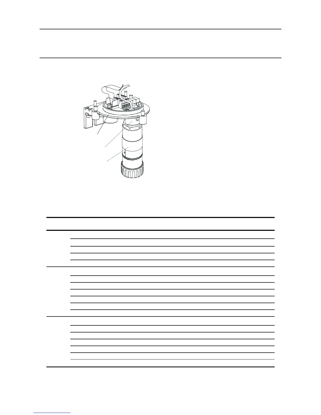
(1) FittheCertiedSensortotheTransmitterUnit.
FeedthesensorcablethroughtheCertiedSensormountingpointatthefrontofthe
TransmitterUnitbase.Screwthesensorrmlyintothemountingpointuntilitisfullyhome.
(2) Connect the sensor wiring.
See the following wiring table and diagram.
Terminal Function Colour Recommended
Number Wire Length
SK3 1 CAN_L White 40mm
(Sensor)
2 CAN_H Green 40mm
3 +V Red 40mm
4 0V Black 40mm
5 Screen 40mm
SK4 1 NET1 60mm
(Comms
2 NET2 60mm
and
3 Ground 50mm
Power)
4 4-20mA- 50mm
5 4-20mA+ 50mm
6 0V 50mm
7 +24Vdc(18-32Vdc) 50mm
SK6 1 Fault 50mm
(Relays)
2 Faultcommon 50mm
3 Alarm1 50mm
4 Alarm1common 50mm
5 Alarm2 50mm
6 Alarm2common 50mm
G - Earth Green/Yellow
Certified Sensor
mounting point
Certified Sensor

 Loading...