5. MAINTENANCE
5.2 MAINTENANCE PROCEDURES /PARTS REPLACEMENT
The following sections describe how to carry out the tasks listed in the maintenance schedule
and how to replace parts suggested by Fault Diagnosis in Chapter 4. It tells how to change the
followingitems:
• Certied Sensor Filter
• Certied Sensor Cartridge
• Certied Sensor
• Transmitter Unit Front Panel Assembly
• CSA Transmitter Unit User Interface Cover Assembly
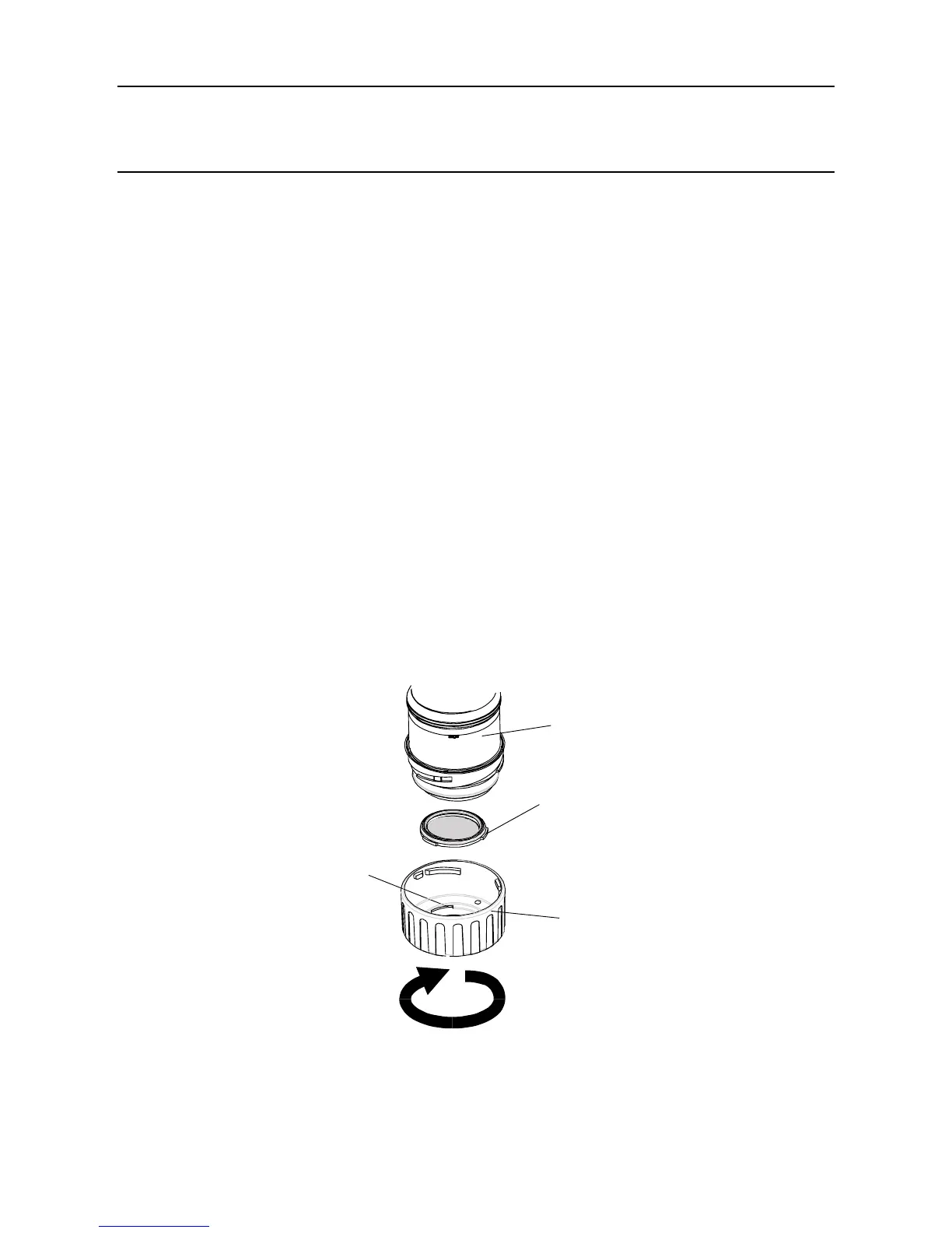
5.2.1 Changing the Certied Sensor Filter
TheCertiedSensorlterislocatedinthesensorcaporaccessoryattachedtotheendofthesensor
body.Thisprocedureallowstheltertobesafelychangedwiththeunitpowered-up.
Note: Beforestartingtheprocedurecheckthatthenewlteristhecorrecttypefortheapplication.
Threeltertypesareavailable:Mesh,HydrophobicandCarbon(seeChapter 2 and
Appendix C).
Toreplacetheltercarryoutthefollowingprocedure:
(1) RemovetheCertiedSensorcaporaccessoryfromthesensorbody.
Rotate the cap or accessory in an anticlockwise direction by 1/4 turn to release the bayonet
ttingandpulloff.
(2) Removetheexistinglter.
Thelterisheldinplaceinthecapbyitsthreelugs.Carefullyprisethelterfreefromthelug
location points in the cap or accessory.
Sensor body
Filter
lug location
Filter
Sensor cap
or

 Loading...