3.1.1 Installing the Transmitter Unit
Cautions:
1. Observe precautions for handling electrostatic
discharge sensitive devices.
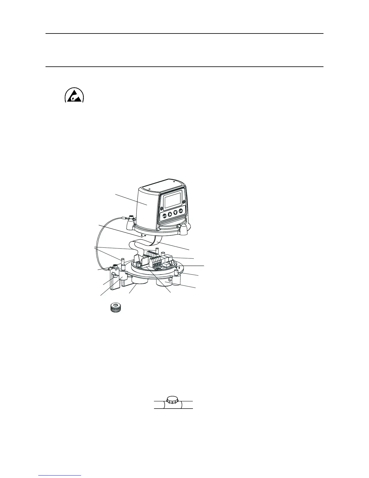
2. EnsurethattheApexTransmitterUnitamepathisnotdamagedduringthisprocedure.
TheamepathisformedbythematingsurfacesoftheApexTransmitterUnittopand
base (see diagram).
(1) Isolate all associated power supplies and ensure that they remain OFF during the installation
procedure. Ensure a gas free atmosphere.
(2) Attach the Apex Transmitter Unit to the supporting structure.
Drill two mounting holes (68mm apart) and use the unit’s mounting slots in the base with
either two M10 bolts or a single 10mm U-bolt Cable/conduit entry sealing plug
Topretaining
cable
Unit top
ZIF
Locating
pins
External
earth
Unit base
Certified
Sensor mounting
point
Cable/conduit
entry (2 off)
Captive bolt
(3 off)
Interconnect PCB
Ribbon cable
Flamepath
Flame-
path
screw
(3) Detach the top of the Transmitter Unit.
Unscrew the three captive M8 bolts in the base. Support the top and let the metal retaining
cable, attaching the top to the base, hold the top. Take care not to damage or strain the
ribbon cable between the top and the base.
(4) Fitandconnecttheeldwiring.
See the subsequent wiring table and diagram. Use either:
Conduit - using one or both of the 3/4 NPT conduit entries. Ensure that a conduit sealing
ttingisinstalledwithin460mmoftheenclosureonallconduitruns.
3. INSTALLATION

 Loading...