3. INSTALLATION
(5) ReconnecttheyingleadplugandsocketconnectingtheMainPCBtothetop.
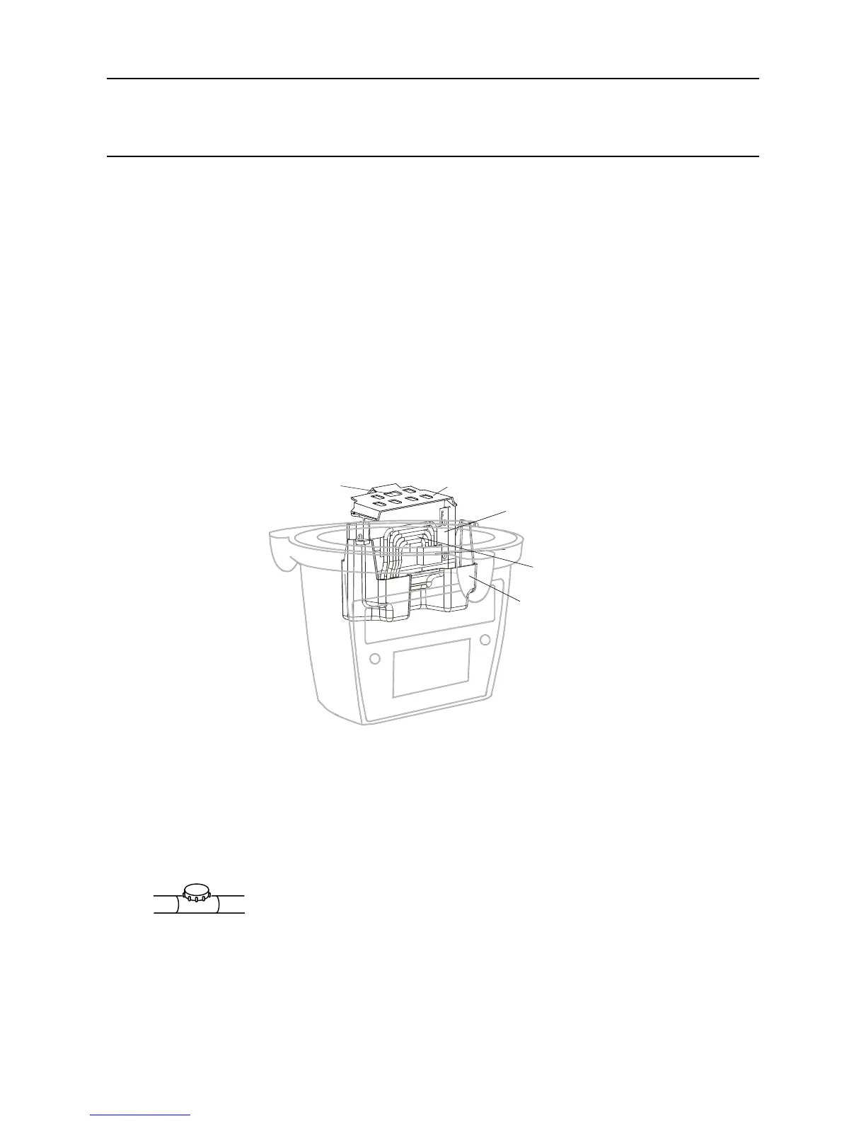
3.3.4 Retting the Main PCB Assembly into the Top
(1) RettheMainPCBPottedassemblywithCommunicationBoardintothetop.
Reversetheremovalprocedure.Theassemblyshouldbettedsothatthecommunications
board is on the same side as the LCD display with the ribbon cable at the top.
(2) RetthePCBBafe.
Caution:Whenrettingthepartsintothetoptakecarenottodamagetheyinglead
plug assembly wires.
EnsurethattheverticalpartofthebafegoesbetweentheMainPCBandtheyinglead
(see diagram).
PushtheCommunicationBoardearthleadthroughthetopmiddleholeinthebafe.
Securetheearthleadunderoneofthetwobafesecuringscrews.Tightenthescrewsto
1.0Nm (0.74 foot-pounds).
3.3.5 Connecting the LonWorks Network Wiring
(1) FitandconnectthecommunicationnetworkeldwiringtoSK4 in the base of the
Transmitter Unit.
Refer to the table and diagram for wiring details. Use either:
Conduit - using one or both of the 3/4 NPT conduit entries. Ensure that a conduit sealing
ttingisinstalledwithin18"oftheenclosureonallconduitruns.
Cable-usinganysuitableameproofcableentrydevicecertiedasEquipmenttoDirective
94/9/EC(ATEX).
Note: Allunusedcable/conduitentriesmustbesealedwithasuitablecertiedsealingplug(one
plug is supplied with the Apex Transmitter Unit).
Main PCB
Potted

 Loading...