3. INSTALLATION
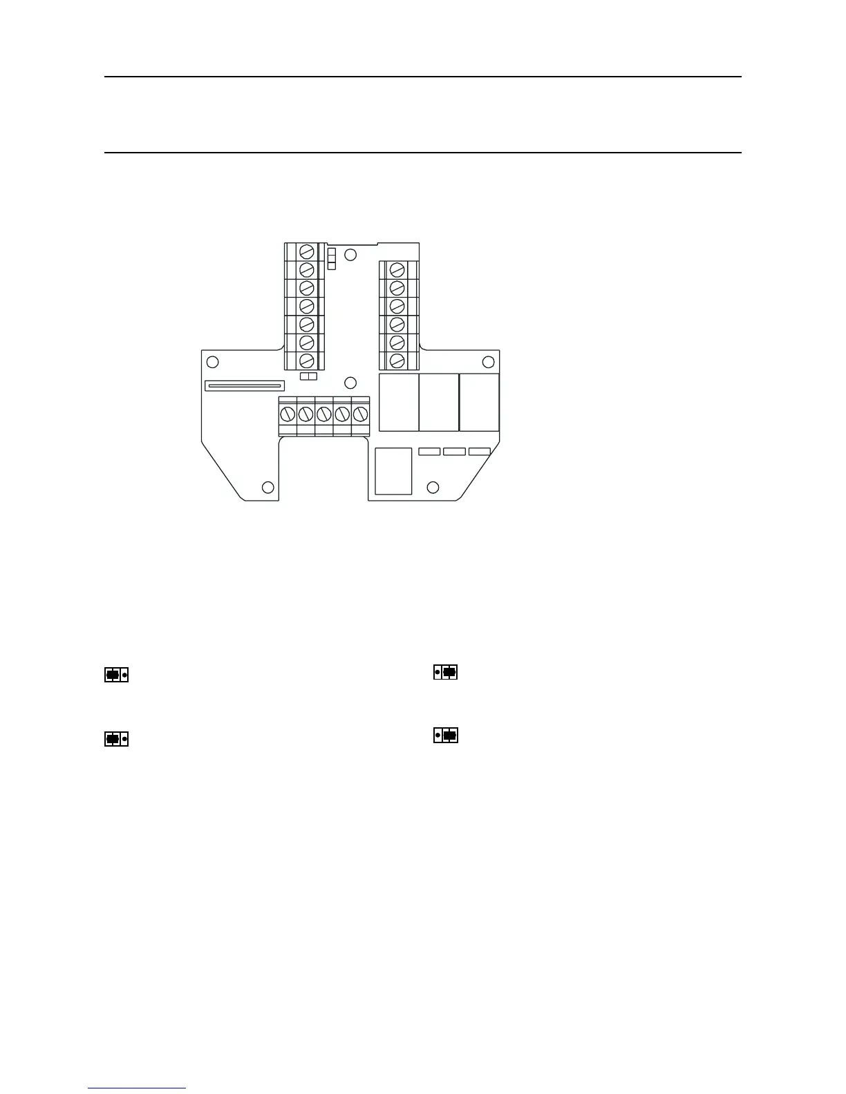
3.1.4 Transmitter Unit Conguration
Caution: Do not change either Relay or 4-20mA link setting while unit is powered up.
Thefollowinginformationspeciestheunitcongurationoptions.
Relays
Links J1, J2 and J3 set the contact operation for the Fault, Alarm 1 and Alarm 2 relays respectively.
J1 (Fault relay - normally energised)
Normally open (default)
Normally closed
J2 and J3 (Alarm 1 and 2 Relays - normally de-energised)
Normally open (default) Normally closed
Note: Relay states shown are the shelf state. Relay contacts are rated at 100mA (min), 2A (max),
30Vdc non-inductive*. HIGHER VOLTAGES MUST NOT BE USED
(*ULspecication:28Vdc,1A)
J1 J2 J3
J4
J5
J1 J2

 Loading...