12 LDM Series Instruction Manual — P/N 15885:H3 8/12/2019
LDM Features The LDM-R32
Keylock Control Switch Security
A UL listed key-lock switch wired to J4 on the LDM-32 should be used to provide access security
for all control switches wired to that set of LDM modules. Control switches will not function
when the key-lock switch is in its closed position.
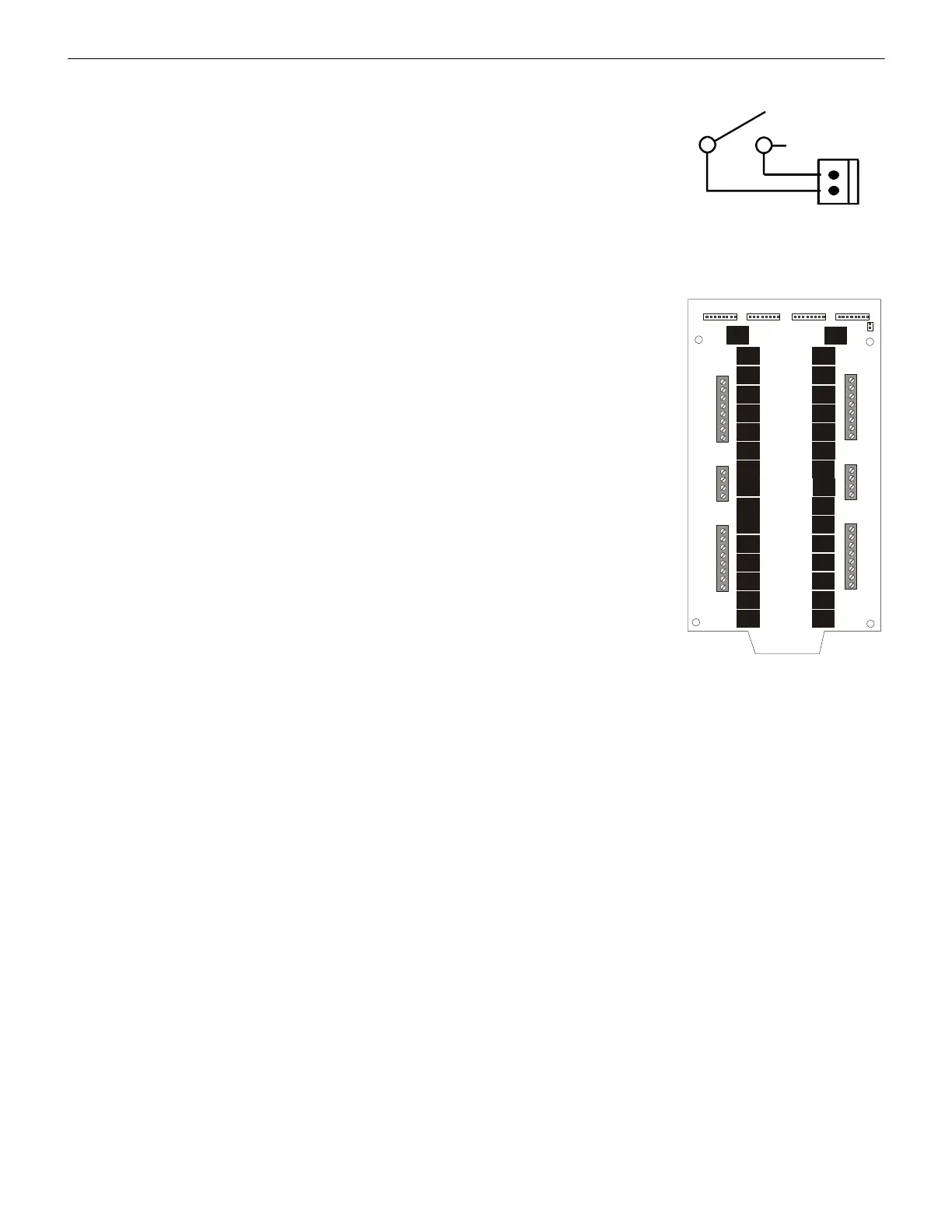
2.8 The LDM-R32
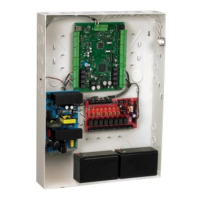
The LDM-R32 Relay Expander Module provides the LDM-32 or LDM-E32 with 32 dry Form-A
(normally open) contacts. The relay module serves as a slave to the particular lamp driver annun-
ciator it is connected to - instead of driving lamps or LEDs, the alarm and/or trouble signals from
the LDM-32 and LDM-E32 modules are used to activate the relays on the LDM-R32. A maxi-
mum of two of these relay modules can be supported by an LDM-32/LDM-E32 operating in
alarm-only mode, providing a maximum of 64 alarm relays. In alarm/trouble mode, one, two or
four LDM-R32 modules may be connected to LDM-32/LDM-E32s, providing a maximum of 64
alarm and 64 trouble relays. Includes mounting hardware, one Relay Power Cable and four Relay
Expander Ribbon cables for connection to the master LDM-32/LDM-E32 module.
K1
K2
K3
K4
K5
K6
K7
K8
K9
K10
K11
K12
K13
K14
K15
K16
1
1
8
1
1
1
2
2
7
2
2
2
3
3
6
3
3
3
4
4
5
4
4
4
5
5
4
5
6
6
3
6
7
7
2
7
8
8
1
8

 Loading...