LDM Series Instruction Manual — P/N 15885:H3 8/12/2019 21
Section 5: Operating the Lamp Driver Module
5.1 LAMP TEST/ACKNOWLEDGE
A separate, dedicated lamp test switch is required for each LDM-32 and LDM-E32. A switch installed for LAMP TEST/ACKNOWL-
EDGE performs two functions:
1. When pressed, it will light all LEDs wired to the specific LDM module (except the On Line LED) and will sound the integral piezo
(if enabled) for as long as the switch is held down. The Lamp Test switch will light only the LEDs on the module to which it is wired.
2. The switch connected to the LDM-32, when pressed, acknowledges all status changes (for both the LDM-32 and any LDM-E32
expanders). Flashing LEDs will latch on solid and the piezo will be silenced.
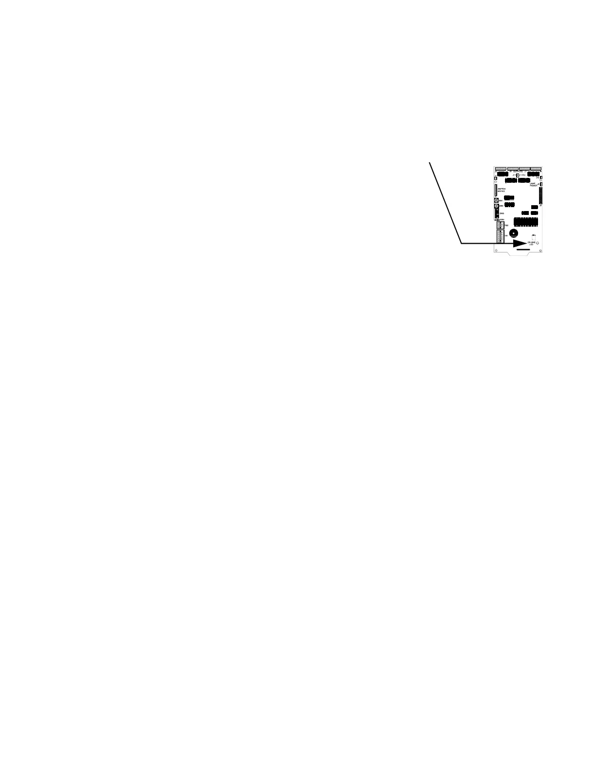
5.2 On Line LED
This green LED, located in the lower right corner of the LDM-32 and LDM-E32 (see Figure
2.1 and Figure 2.2), flickers during communication with the host control panel.
5.3 Graphic Annunciator Lamps/LEDs
To adhere to standard fire alarm control panel convention and remain consistent with other products that may exist in the system, the fol-
lowing color convention is employed:
• Red Alarm LEDs
To indicate an alarm condition for an Initiating Device Circuit, software zone or addressable initiating device.
• Yellow Trouble LEDs
To indicate a trouble condition exists on an initiating or indicating device circuit or zone. Yellow trouble LEDs also are used to
indicate general system trouble conditions such as low battery, earth fault, general system trouble, etc.
• Green Controlled Output LEDs
Indicates that power is applied or that the controlled output circuit or device has been activated. Applicable to notification
appliance, relay, speaker, telephone, and time control circuits.
The graphic annunciator may contain a yellow System Trouble LED and a red System Alarm LED which will light for all trouble or alarm
conditions (respectively) in the system (not just for those points of zones mapped to the LDM annunciator/expanders).

 Loading...