16 LDM Series Instruction Manual — P/N 15885:H3 8/12/2019
Section 4: Wiring Considerations
4.1 Limits
A maximum of 32 LDM-32s may be connected to the EIA-485 bus, but if other types of devices are also connected to the EIA-485
bus, the maximum number of LDM-32s must be reduced by the total of such devices. Total annunciation and switch capability depend
upon the number of LDM-E32 expander modules used.
4.2 Wire Runs
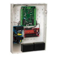
Communications between the Fire Alarm Control Panel and the LDM is accomplished over a two-wire EIA-485 serial communications
bus which must be power-limited. Communications between the host FACP and LDMs is supervised by the Fire Alarm Control Panel.
Power supplied by the host control panel or external power supply must be power-limited. It is inherently supervised (loss of power also
results in a communication failure at the control panel). Refer to appropriate control panel manual for UL Power-limited Wiring Require-
ments.
4.3 EIA-485 Wiring Specifications
The EIA-485 circuit cannot be T-tapped; it must be wired in a continuous fashion from the control panel to the LDMs. The maximum
wiring distance between the panel and LDMs is 6,000 feet (1,800 m). The wiring must be an 18 AWG to 14 AWG (0.75 to 2.00 mm2)
twisted shielded pair cable having a characteristic impedance of 120 ohms, +/- 20%. Limit the total wire resistance to 100 ohms on the
EIA-485 circuit, and 10 ohms on the LDM power circuit. Do not run cable adjacent to, or in the same conduit as, 120 volts AC service,
noisy electrical circuits that are powering mechanical bells or horns, audio circuits above 25 VRMS, motor control circuits, or SCR
power circuits.
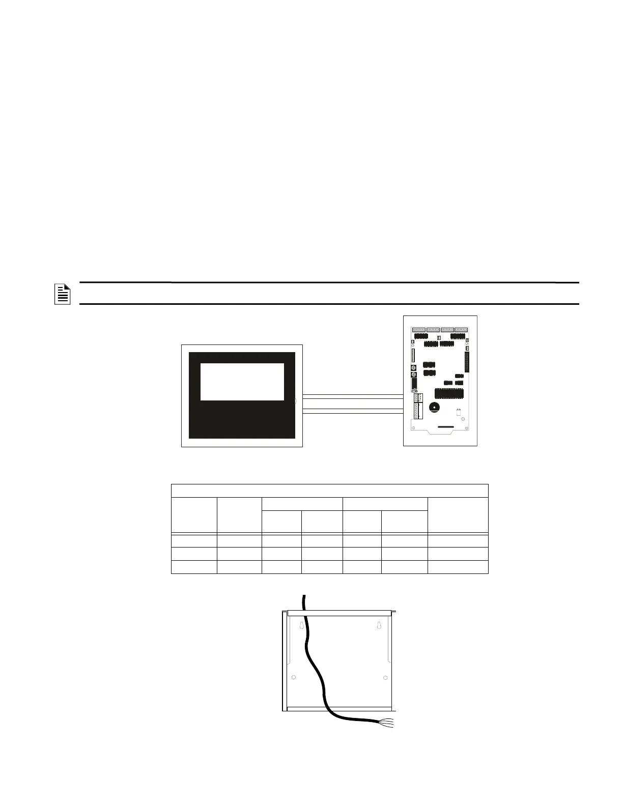
Mount cabinet or backbox and draw all wiring into enclosure.
NOTE: All enclosures, including the FACP backbox, must be connected to earth ground! Never use the shield for grounding purposes.
Terminate the EIA-485 shield at the Fire Alarm Control Panel only.
STANDARD ANNEALED COPPER WIRE
Wire Size
A.W.G.
Diameter
in Mils
Cross Section Ohms per 1000 feet Pounds
per 1000 ft
Circ.
Mils
Sq. Inch @ 77 F. @ 149 F.
14 64 4110 0.00323 2.58 2.97 12.4
16 51 2580 0.00203 4.09 4.73 7.82
18 40 1620 0.00128 6.51 7.51 4.92
+5 VDC
J6
J5
J4
J1
SW1
SW2
SW3
SW4
TB2
TB1
Fire Alarm Control Panel
Lamp Driver
Two-Wire EIA-485
Circuit
Maximum 6,000 ft.
(1,800 m)
Power for LDM
18 to 14 AWG
(0.75 to 2.00 mm
2
)
Figure 4.1 EIA-485 Communications
Figure 4.2 Wiring the Enclosure

 Loading...