LDM Series Instruction Manual — P/N 15885:H3 8/12/2019 23
Section 7: Electrical Ratings and Current Calculations
7.1 Lamp Driver Electrical Ratings
LDM modules may use either 24 VDC (regulated) or internal 5 VDC for powering connected LEDs. 5 volt usage conserves power but is
limited in the current available to drive the LEDs. Refer to Section 4, Figure 4.7 and Figure 4.8 for connection illustrations.
Maximum Current per Driver: 100 mA (external circuit must limit current)
Maximum Voltage rating per output driver: 30 VDC
Supervised circuit (typical rating): 5 volts DC @ 0.5 mA
Bipolar Darlington Open Collector NPN Transistor
7.2 Supervision of LDM points
Any LEDs or lamps connected to the LDM-32 or LDM-E32 are not supervised for failure. Therefore, all LEDs or lamps, must be located
in the same room as the LDM modules.
7.3 Calculating LDM Series Standby and Alarm Currents
Current Draw for LED Power @ 24 VDC
1. Enter Standby Total obtained here into the standby calculation tables.
2. Enter Alarm Current obtained here into the alarm calculation tables.
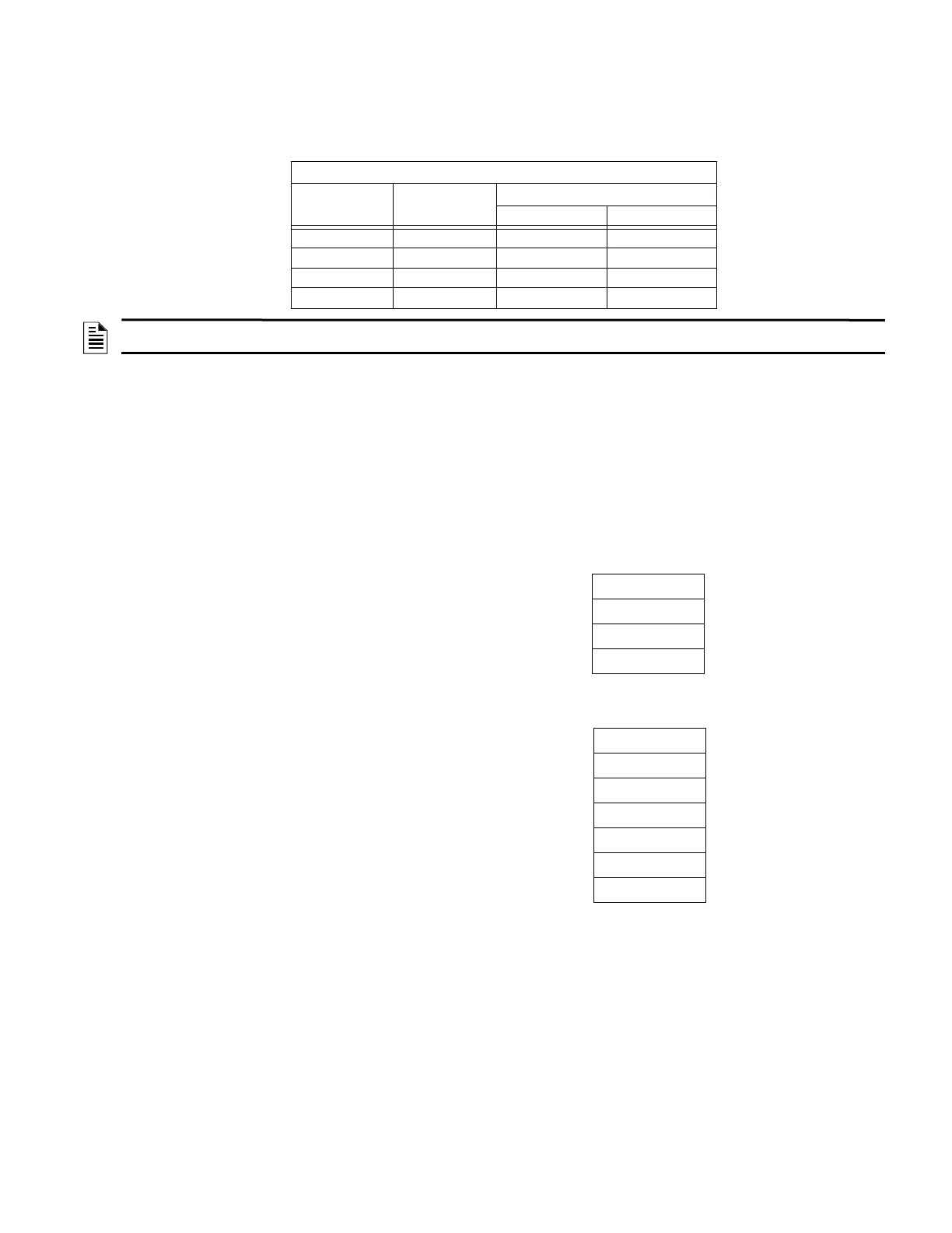
5-Volt LED Power Limitations
LED current
desired (mA)
Max # of LEDs
Number of Modules
LDM-32 LDM-E32
2 130 1 3
566 1 1
10 34 1 0
20 17 1/2 0
NOTE: The LDM-32 drives 32 LEDs and each LDM-E32 drives 32 more LEDs. An LDM system configured for Alarm and Trouble Display
Mode and employing three expanders could have as many as 128 LEDs, all of which are activated during Lamp Test.
Standby Current
[ ] # of LDM-32 Modules
X
40 mA
1
1 The 0.040 amps can be reduced to 0.030 for modules with Piezo disable or Flash Inhibit selected.
=
[ ] # of LDM-E32 Modules
X2 mA
=
Standby Total
24VDC
=
Alarm Current
[
X 56 mA
=
[
X 18 mA
=
[
X 288 mA
=
[
X [ ] ma per LED
=
[
] # of LDM-32 Modules
] # of LDM-E32 Modules
] # of LDM-R32 Modules
] # of LEDs
1
] # of LEDs
2
1 Use this line for calculations if LEDs are powered from 24 VDC source.
2 Use this line for calculations if LEDs are powered from the 5 VDC source from J1 on the LDM-32.
The LDM series annunciators draw their power from the Fire Alarm Control Panel and must be considered when calculating
primary and secondary power requirements. Refer to the installation manual for the particular control panel employed for the calcu-
lation of power requirements for the entire system.
X [{ } mA/3]
=
Alarm Total
24VDC
=

 Loading...