20 LDM Series Instruction Manual — P/N 15885:H3 8/12/2019
Wiring Considerations Control Switch Wiring
4.10 Control Switch Wiring
Optional zone/point control switches must be momentary type. Wiring from the LDM to the control switches must be in conduit and in
the same room as the LDM since the wires are not supervised. Use the cables supplied in the cable kits to wire the control switches.
1
Each LDM must be set for Alarm/Trouble Mode by positioning slide switch SW4 to the right, for the optional control switches to func-
tion (the Acknowledge/Lamp Test switch will work in either mode). In this configuration, each LDM-32 and LDM-E32 provides 16
alarm drivers, 16 trouble drivers and 16 control switches. The alarm and trouble drivers are assigned to host FACP zones/points via user
setup/installation. See tables in the appendix for the appropriate FACP for additional information. Not all switches must be used -
switches can be wired only for desired functions. To determine the function of each switch and driver in a specific FACP application,
refer to the Appendices in this manual and the appropriate FACP Installation Manual.
J11
+5
+24
Common
J6
J5
J4
SWITCH
MATRI X
LAMP
POWER
OUTPUTS
J7
J8
J10
J9
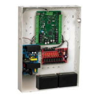
Note: All LEDs must be in the same room as the LDM modules.
Point Status LEDs:
Use red for alarm points,
yellow for trouble points, and
green for output points
Use 10K W, 1/4 watt resistors for
each point if using 2 mA LEDs.
Custom
Graphic
Display
System
Trouble LED
(Yellow)
Wiring is not
supervised
Figure 4.9 Typical LDM-to-Graphics Display Connection @ 24 VDC
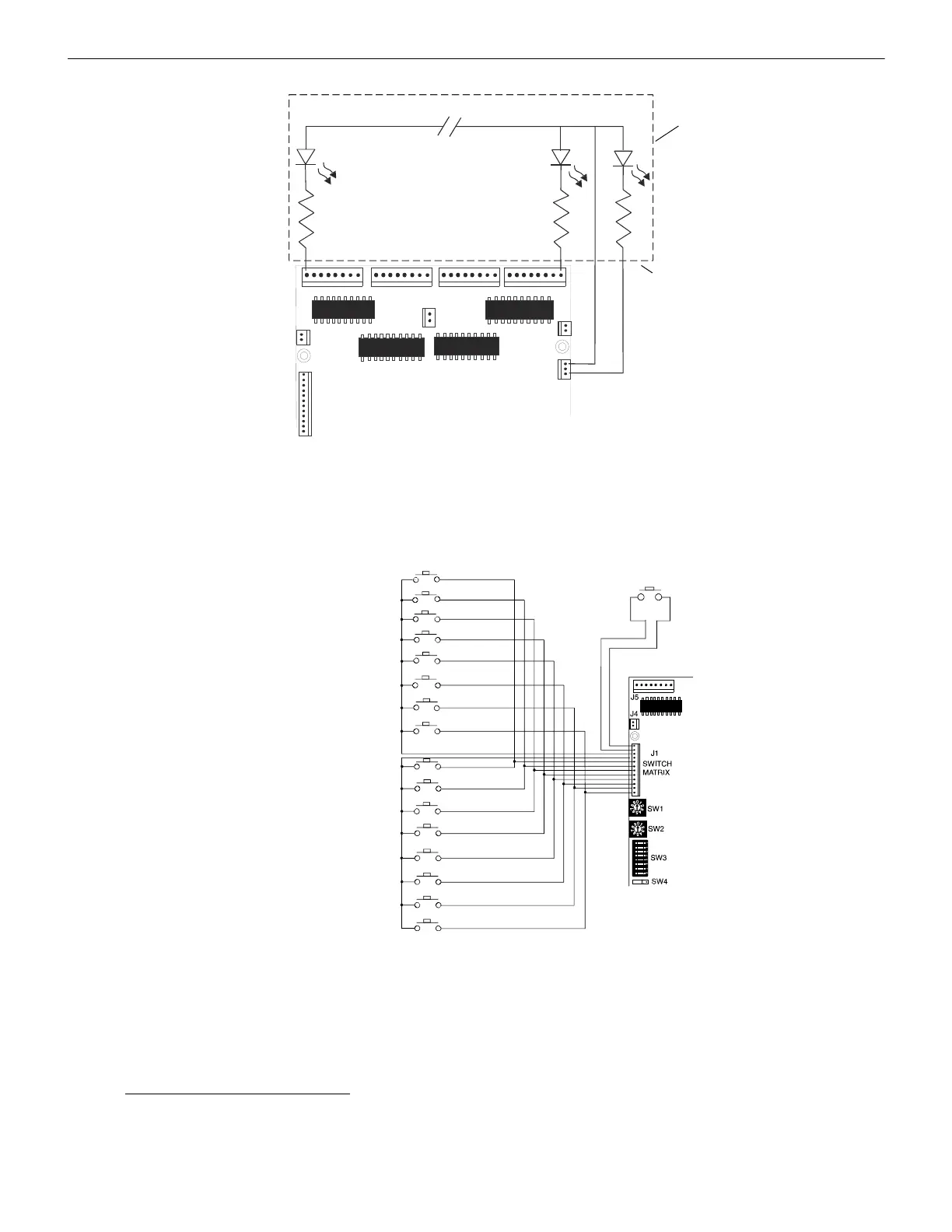
1. Switches must be UL listed to switch 5 volts DC @ 0.5mA. Switches must be key-lock type, secured in a locked enclosure
or a security key switch must be installed to control access. All switches must be installed in the same room as, and no more
than 20 feet from, the LDM enclosure. Switch wiring must be in conduit.
Acknowledge/ Lamp Test
Switch (momentary)
Switch #16
Switch #15
Switch #14
Switch #13
Switch #12
Switch #11
Switch #10
Switch #9
Switch #8
Switch #7
Switch #6
Switch #5
Switch #4
Switch #3
Switch #2
Switch #1
Figure 4.10 Optional Zone/Point-Control Switch Wiring

 Loading...