LDM Series Instruction Manual — P/N 15885:H3 8/12/2019 25
Configuration for the LDM-32 and System 500 System 500 (UL 8th)
A.5 Configuration for the LDM-32 and System 500
LDM-32 DIP Switch (SW3) settings (for System 500):
1. Relay Control: Future Use - this switch must be set OFF on the System 500.
None One
2. Number of LDM-E32 Expanders Installed: OFF ON
3. Number of LDM-E32 Expanders Installed: OFF ON
4. 8-Point Shift: Set switch ON to shift CPU-500 LED function annunciation out of the first eight annunciator positions on the
LDM-32. This switch is intended for systems between 9 and 16 circuits and employing one LDM-32 module (with no expander)
where annunciation of all circuits is desired.
5. Receive Only: Set this switch ON for each LDM series that will provide the same information as another LDM series in a different
physical location (when two or more sets of LDM series have the same address, all but one must be configured as Receive Only.)
6. Piezo Disable: Set this switch ON to disable the piezo from sounding for any event.
7. Switch Inhibit: To disable the point I/O control switches on the LDMs from functioning, set this switch ON. When inhibited, the
local Lamp Test switch continues to function. In addition, the Acknowledge/Lamp Test switch will function only in a local capacity,
unrecognized by the host System 500.
8. Flash Inhibit: Set this switch ON to disable the flashing of LEDs associated with unacknowledged events. Flash Inhibit also
disables the piezo from sounding. Flash Inhibit must be ON when using the relay expander module (LDM-R32).
A.6 Annunciator Operation
Annunciator points 'track' or follow those System 500 points they are programmed to annunciate; they do not latch. Table A.1 outlines
the annunciation of various System 500 circuits and functions. Note: Control Switches marked 'not used' will still function as local
LAMP TEST or local ACKNOWLEDGE switches for their respective points.
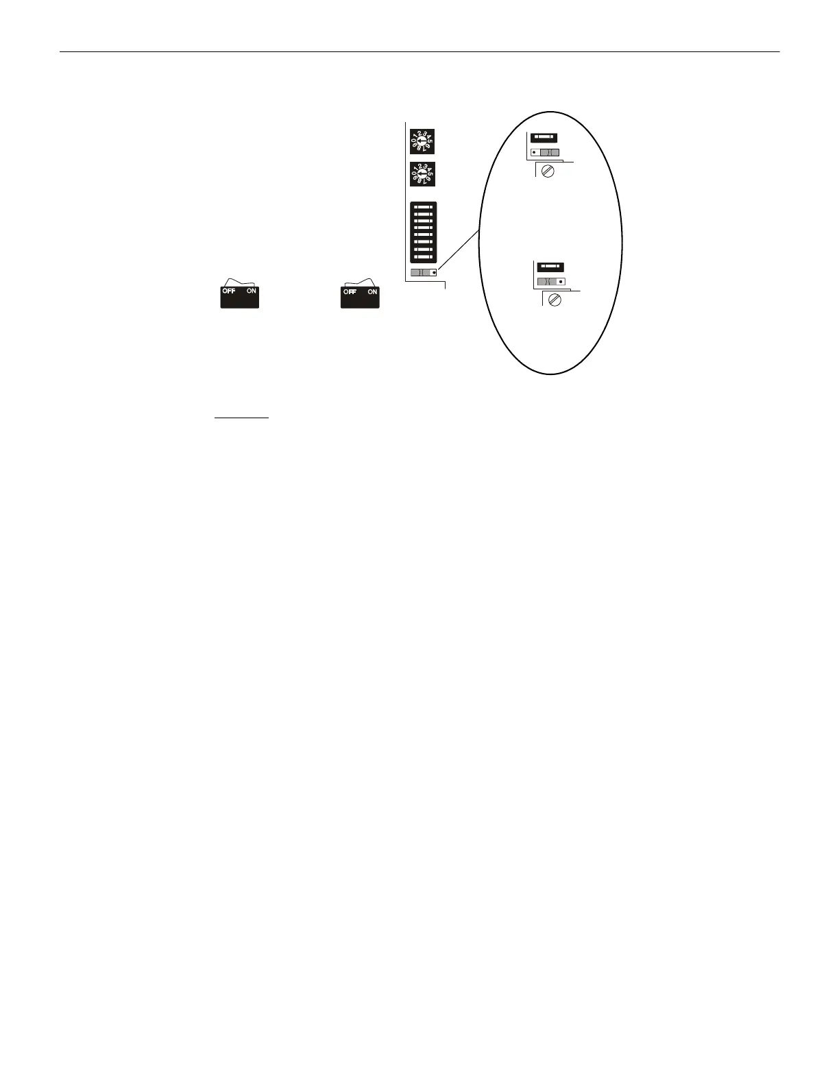
LDM-32
Switch set to
ON position
Switch set to
OFF position
Lamp Driver Address
Set in the range 01-04
Ones
Tens
DIP Switch SW3
(see settings below)
Lamp Driver Mode Switch
SW4
SW4
ALARM/TROUBLE mode
(SW4 set to right side)
ALARM ONLY mode
(SW4 set to left side)

 Loading...