Ethernet
HP Integrity Server
Destination MAC/Source MAC/Destination IP/Source IP
E A 1.1.1.1 1.1.1.2
E B 1.1.1.1 1.1.1.3
E C 1.1.1.1 1.1.1.4
E D 1.1.1.1 1.1.1.5
Destination MAC/Source MAC/Destination IP/Source IP
ARP Table:
1.1.1.1 = E
1.1.1.3 = B
1.1.1.4 = C
1.1.1.5 = D
ARP Table:
1.1.1.1 = E
1.1.1.2 = A
1.1.1.4 = C
1.1.1.5 = D
ARP Table:
1.1.1.2 = A
1.1.1.3 = B
1.1.1.4 = C
1.1.1.5 = D
A E 1.1.1.2 1.1.1.1
B E 1.1.1.3 1.1.1.1
C E 1.1.1.4 1.1.1.1
D E 1.1.1.5 1.1.1.1
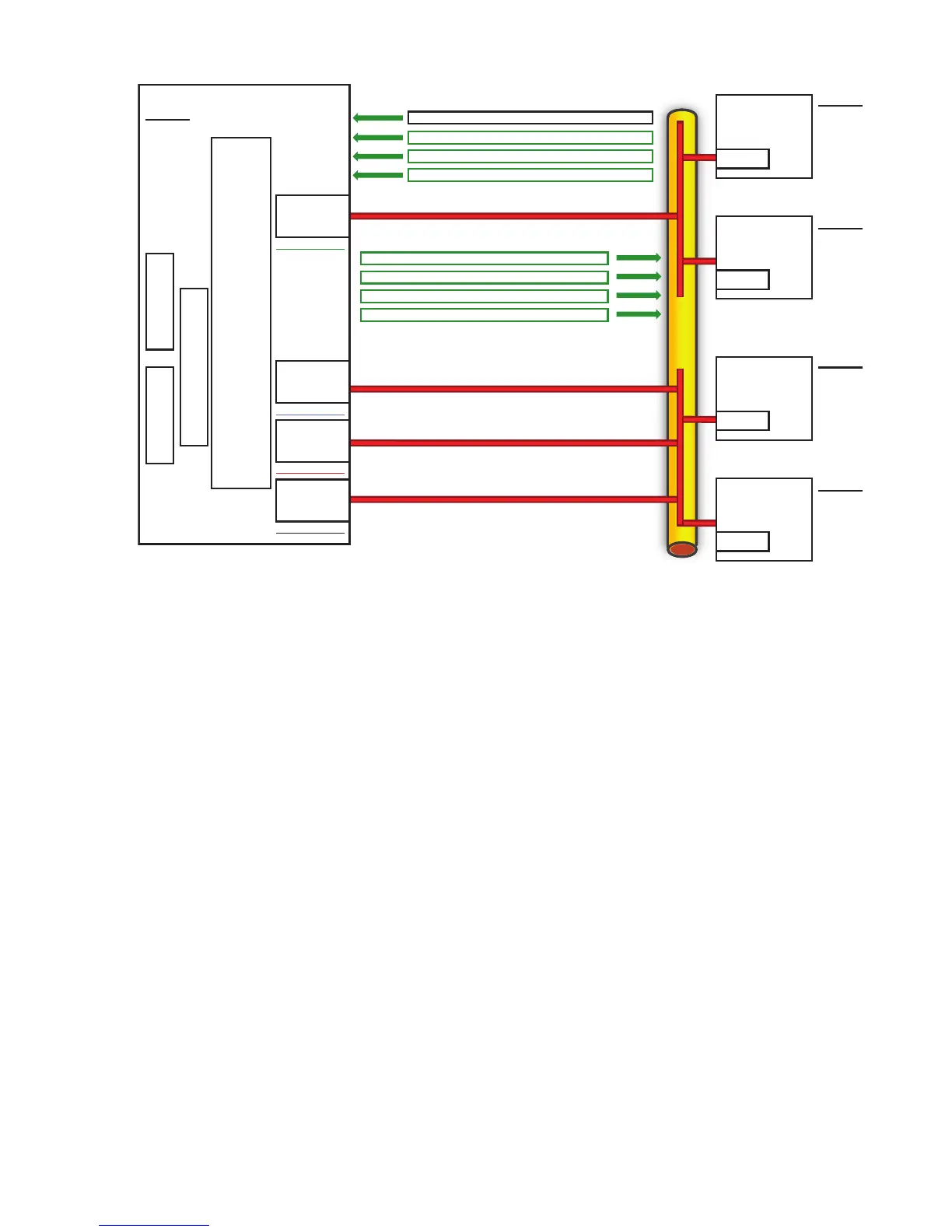
Application #2 Application #1
TCP/IP
TEAMING INTERMEDIATE DRIVER
NFT Team
IP Address = 1.1.1.1
N100NT5.SYS
MAC = E
N100NT5.SYS
MAC = F
N100NT5.SYS
MAC = G
N100NT5.SYS
MAC = H
Non-Primary NIC
Non-Primary NIC
Non-Primary NIC
Client A
IP Address = 1.1.1.2
MAC = A
Client B
IP Address = 1.1.1.3
MAC = B
ARP Table:
1.1.1.1 = E
1.1.1.2 = A
1.1.1.3 = B
1.1.1.5 = D
ARP Table:
1.1.1.1 = E
1.1.1.2 = A
1.1.1.3 = B
1.1.1.4 = C
Client C
IP Address = 1.1.1.4
MAC = C
Client D
IP Address = 1.1.1.5
MAC = D
Primary NIC
Network Addressing and Communication with NFT
Before learning the specifics of NFT and how it communicates on the network, it is recommended
that you thoroughly review this section, “HP Teaming and Layer 2 Versus Layer 3 Addresses”,
in addition to Appendix A “– Overview of Network Addressing and Communication”.
Scenario 4–A: A Device Pings an NFT Team on the Same Layer 2 Network
This section builds on the concepts reviewed in Appendix A “– Overview of Network Addressing
and Communication”, and describes how NFT functions from the network addressing and
communication perspective.
Utilizing a network diagram similar to Figure 4-2, Blue has been modified to be a server utilizing
an HP network adapter team in NFT mode with two network ports in a team (refer to Figure
4-2). The two network ports have MAC addresses of B and E, and are known by a single Layer
3 address of 1.1.1.2. Network port B has been designated as the Primary port in this NFT team.
32 The Mechanics of Teaming for the Advanced User
 Loading...