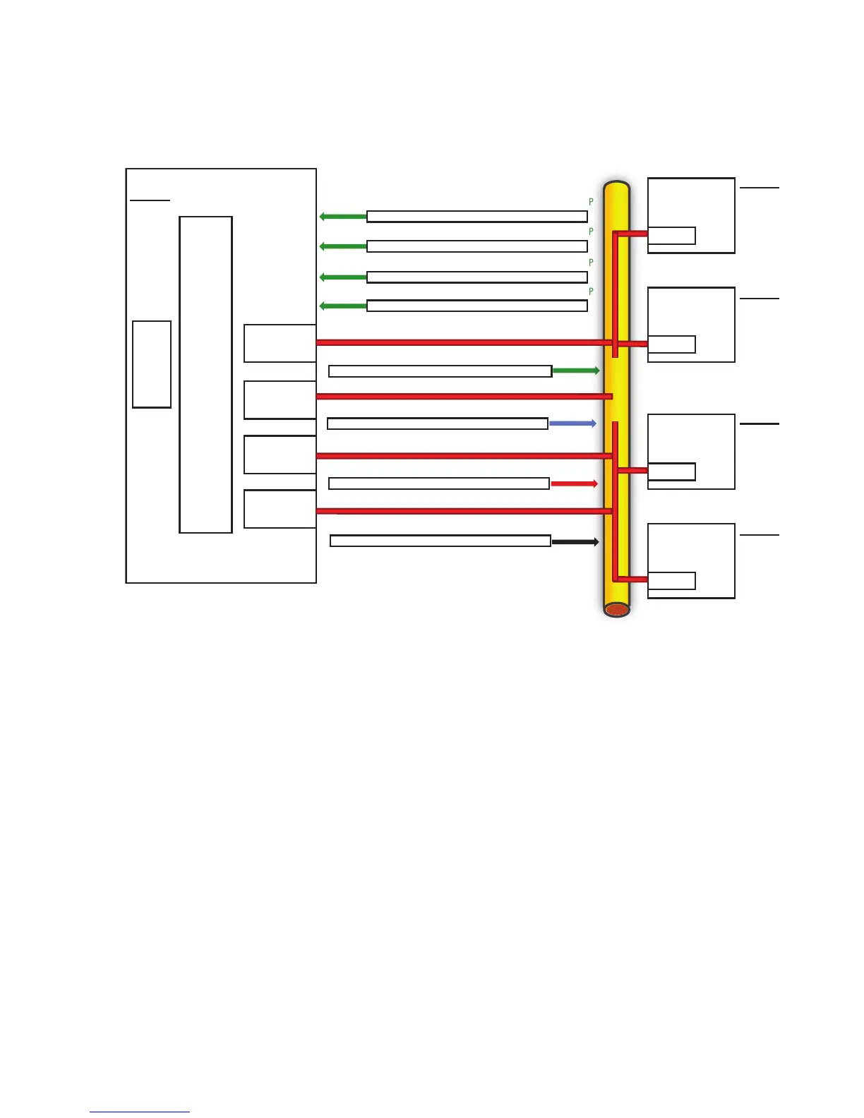
However, traffic received by the server is not load balanced, meaning the Primary teamed port
is responsible for receiving all traffic destined for the server (refer to Figure 4-12). As with NFT,
there are two types of team members, Primary and Non-Primary ports. The Primary port transmits
and receives frames and the non-Primary ports only transmit frames.
Figure 4-12 Overview of TLB communication
HP Proliant
Destination MAC/Source MAC/Destination IP/Source IP
E A 1.1.1.1 1.1.1.2
Destination MAC/Source MAC/Destination IP/Source IP
E B 1.1.1.1 1.1.1.3
Destination MAC/Source MAC/Destination IP/Source IP
E C 1.1.1.1 1.1.1.4
Destination MAC/Source MAC/Destination IP/Source IP
E D 1.1.1.1 1.1.1.5
Destination MAC/Source MAC/Destination IP/Source IP
C G 1.1.1.4 1.1.1.1
Destination MAC/Source MAC/Destination IP/Source IP
D H 1.1.1.5 1.1.1.1
Destination MAC/Source MAC/Destination IP/Source IP
B F 1.1.1.3 1.1.1.1
Destination MAC/Source MAC/Destination IP/Source IP
ARP Table:
1.1.1.1 = E
1.1.1.3 = B
1.1.1.4 = C
1.1.1.5 = D
ARP Table:
1.1.1.1 = E
1.1.1.2 = A
1.1.1.4 = C
1.1.1.5 = D
ARP Table:
1.1.1.2 = A
1.1.1.3 = B
1.1.1.4 = C
1.1.1.5 = D
A E 1.1.1.2 1.1.1.1
TCP/IP
NDIS 5
CPQTEAM.SYS
TLB Team
IP Address = 1.1.1.1
N100NT5.SYS
MAC = E
N100NT5.SYS
MAC = F
N100NT5.SYS
MAC = G
N100NT5.SYS
MAC = H
Client A
IP Address = 1.1.1.2
MAC = A
Client B
IP Address = 1.1.1.3
MAC = B
ARP Table:
1.1.1.1 = E
1.1.1.2 = A
1.1.1.3 = B
1.1.1.5 = D
ARP Table:
1.1.1.1 = E
1.1.1.2 = A
1.1.1.3 = B
1.1.1.4 = C
Client C
IP Address = 1.1.1.4
MAC = C
Client D
IP Address = 1.1.1.5
MAC = D
Ethernet
Network Addressing and Communication with TLB
Before learning the specifics of TLB and how it communicates on the network, it is recommended
that you review and thoroughly understand this section, “HP Teaming and Layer 2 Versus Layer
3 Addresses”, as well as the Appendix, Appendix A “– Overview of Network Addressing and
Communication”.
Scenario 4–B: A Device Pings a TLB Team on the Same Layer 2 Network
This section builds on the concepts reviewed in “Scenario A-1: One Device Pings Another on the
Same Layer 2 Network” in Appendix A, and describes how TLB functions from the network
addressing and communication perspective.
Utilizing a network diagram similar to Figure A-1 in Appendix A, Blue has been modified to be
a server utilizing an HP Integrity Network adapter team in TLB mode with two network ports
in a team (refer to Figure 4-13). The two network ports have Layer 2 addresses of MAC B and
MAC E, respectively, and are known by a single Layer 3 address of 1.1.1.2. Network port B has
been designated as the Primary port in this TLB team.
58 The Mechanics of Teaming for the Advanced User
 Loading...