the Automatic mode. By deploying this method now, future upgrades will automatically take
advantage of the new intelligence.
TLB TCP Connection Method
TCP Connection is also a load-balancing method that is designed to preserve frame ordering.
This method will load balance outbound traffic based on the TCP port information in the frame’s
TCP header. This load-balancing method combines the TCP source and destination ports to
identify the TCP conversation. Combining these values, the algorithm can identify individual
TCP conversations (even multiple conversations between the team and one other network device).
The algorithm used to choose which teamed port to use per TCP conversation is similar to the
algorithms used in the “TLB Destination IP Address Method” and “TLB Destination MAC
Address Method” sections below.
If this method is chosen, and the frame has an IP header with and IP address but not a TCP
header, then the frame is load balanced by destination IP address (refer to “TLB Destination IP
Address Method” below). If the frame doesn’t have an IP header, the frame is load balanced by
destination MAC address (refer to “TLB Destination MAC Address Method” below).
TLB Destination IP Address Method
Destination IP Address is a load-balancing method that will attempt to preserve frame ordering.
This method makes load-balancing decisions based on the destination IP address of the frame
being transmitted by the teaming driver. The frame’s destination IP address belongs to the
network device that will ultimately receive the frame. The team utilizes the last three bits of the
destination IP address to assign the frame to a port for transmission.
Because IP addresses are in decimal format, it is necessary to convert them to binary format. For
example, an IP address of 1.2.3.4 (dotted decimal) would be 0000 0001 . 0000 0010 . 0000 0011 .
0000 0100 in binary format. The teaming driver only uses the last three bits (100) of the least
significant byte (0000 0100 = 4) of the IP address. Utilizing these three bits, the teaming driver
will consecutively assign destination IP addresses to each functional network port in its team
starting with 000 being assigned to network port 1, 001 being assigned to network port 2, and
so on. Of course, how the IP addresses are assigned depends on the number of network ports in
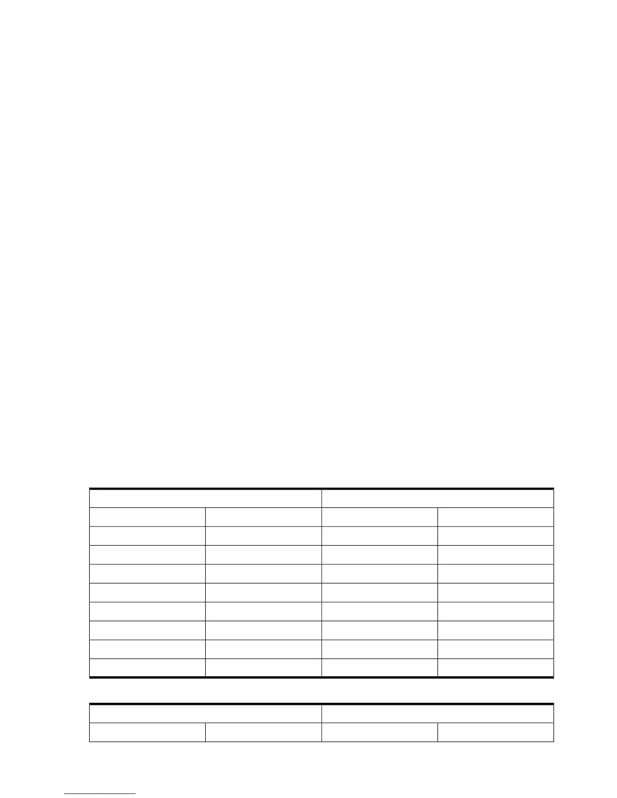
the TLB team and how many of those ports are in a functional state (refer to Table 4-9).
Table 4-9 Load Balancing based on Destination IP Address (two- and three-port teams)
Three-Port TeamTwo-Port Team
Transmitting PortDestination IPTransmitting PortDestination IP
network port 1000network port 1000
network port 2001network port 2001
network port 3010network port 1010
network port 1011network port 2011
network port 2100network port 1100
network port 3101network port 2101
network port 1110network port 1110
network port 2111network port 2111
Table 4-10 Load Balancing based on Destination IP Address (four- and five-port teams)
Five-Port TeamFour-Port Team
Transmitting PortDestination IPTransmitting PortDestination IP
62 The Mechanics of Teaming for the Advanced User
 Loading...