2-2
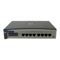
Installing the Switch 408
Installation Procedures
Japan Power Cord Warning
Installation Procedures
Summary
Follow these easy steps to install your switch. The rest of this chapter
provides details on these steps.
1. Prepare the installation site. Make sure of the following:
• the network cabling is the correct type and length. See page
2-5.
• the network topology is correct. See page 2-10.
• no devices connected to the switch have a fixed full-duplex
configuration (they must be able to auto-negotiate the duplex
mode or be fixed at half duplex). See page 2-4.
See page 2-3 for installation precautions.
2. Verify that the switch passes its self test. This is a simple
process of plugging the switch into a power source and observing
that the LEDs on the switch’s front panel show correct operation.
See page 2-7.
3. Mount the switch. The Switch 408 can be mounted on any
horizontal surface. The optional mounting kit (5183-7210)
provides other options including mounting two switch units side-
by-side in a standard 19-inch telco rack or equipment cabinet.
4. Connect power to the switch. Once the switch is mounted, plug
in the AC power adapter. See page 2-9.
 Loading...