1
2
3
4
5
6
7
l0064
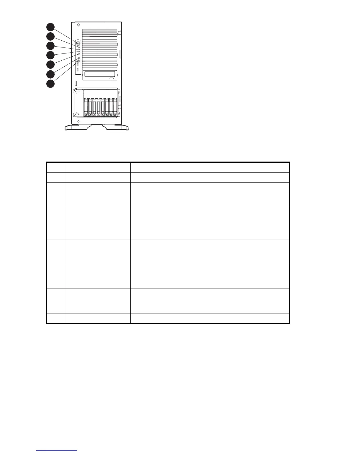
Figure 3 Front panel controls and indicators
Table 3 Front panel controls and indicators
Item
Description Status
1
Power On/Standby button N/A
2
Power On/Standby LED
Green = Power on
Amber = System shut down, but power still applied
Off = No power
3
Internal health LED Green = Normal
Amber = System health is degraded.
Red = System health is critical
Off = Normal (when in standby mode)
4
External h
ealth L ED (power
supply)
Green = Nor
mal
Amber = Pow
er redundancy failure
Red = Criti
cal power supply failure
5
NIC 1 activity LED
Green = Network link
Flashing = Network link and activity
Off = No network connection
6
UID LED
Blue = Activated
Flashing = System remotely managed
Off=Deactivated
7
UID button
N/A
24
Storage server features a nd specifications
 Loading...