Arr ay s
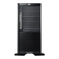
See Figure 9. With an a rray controller installed in the system, the capacity of several physical drives
(P1–P3) can be logically combined into one or more logical units (L1) called arrays. When this is
done, the read/write heads of all the constituent physical drives are active simultaneously, dramatically
reducing the ov
erall time required for data transfer.
NOTE:
Depending on the storage server model, array con figuration may not be possible or necessary.
P1 P3P2
Figure 9 Con figuring arrays from physical drives
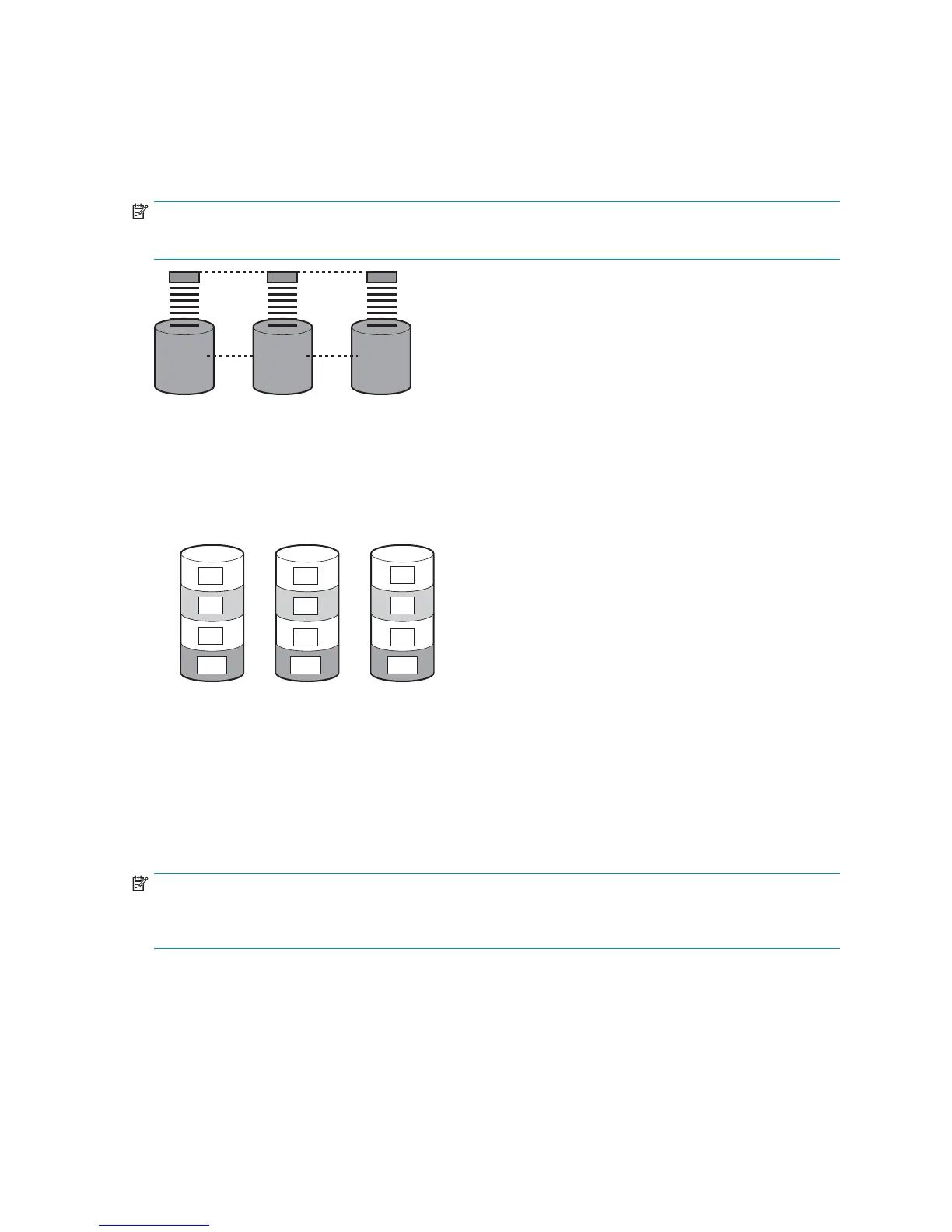
Because the read/write heads are simultaneously active, the same amount of data is written to each
drive during any given time interval. Each unit of data is termed a block. The blocks form a set of data
stripes over all the hard drives in an array, as shown in Figure 10.
S1
S2
S3
S4
B1
B4
B7
B2
B5
B8
B11B10 B12
B6
B3
B9
Figure 10 RAID 0 (data striping) (S1-S4 ) of data blocks (B1-B12)
For data in the array to be readable, the data block sequence within each stripe must be the same.
This sequencing process is performed by the array controller, which sends the data blocks to the drive
write h ea ds in the correct order.
A natural consequence of the striping process is that each hard drive in a given array contains the
same number of data blocks.
NOTE:
If one hard drive has a larger capacity than other hard drives in the same array, the extra capacity is
wastedbecauseitcannotbeusedbythearray.
Fault tolerance
Drive failure, although rare, is potentially catastrophic. For example, using simple striping as shown in
Figure 10, failure of a ny hard drive leads to failure of all logical d rives in the same array, and hence to
data loss.
To protect against data loss from hard drive failure, storage servers should be configured with fault
tolerance. HP recommends adhering to RAID 5 configurations.
HPProLiantML350G5StorageServer
37
 Loading...