216 Fabric OS Administrator’s Guide
53-1002446-01
Logical fabric overview
10
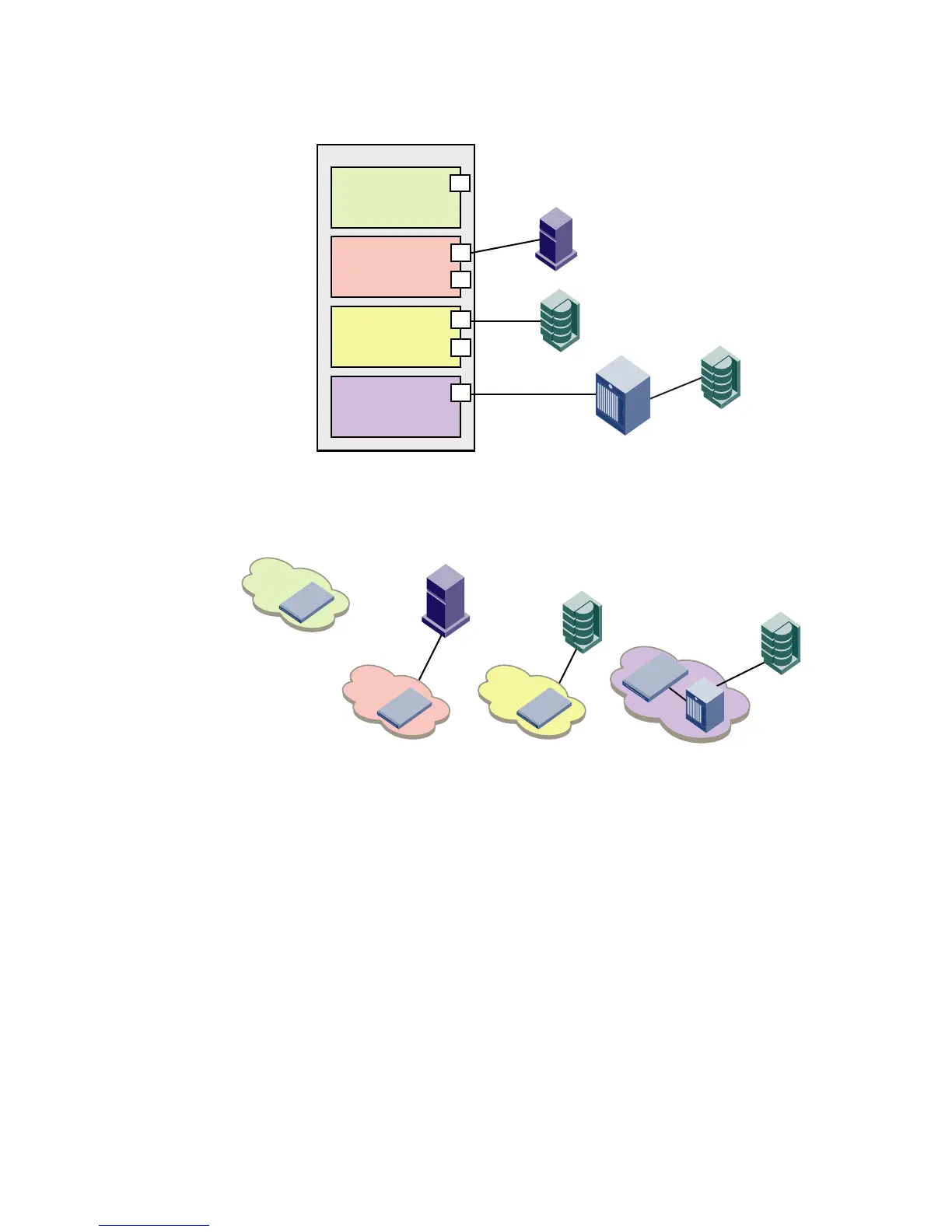
FIGURE 21 Logical switches connected to devices and non-Virtual Fabrics switch
Figure 22 shows a logical representation of the physical chassis and devices in Figure 21. As
shown in Figure 22, the devices are isolated into separate fabrics.
FIGURE 22 Logical switches in a single chassis belong to separate fabrics
For information on allowing device sharing across fabrics in a Virtual Fabrics environment, refer to
“FC-FC routing and Virtual Fabrics” on page 501.
Logical fabric overview
A logical fabric is a fabric that contains at least one logical switch. The four fabrics shown in
Figure 21 and Figure 22 are logical fabrics because they each have at least one logical switch.
You can connect logical switches to non-Virtual Fabrics switches and to other logical switches.
You connect logical switches to non-Virtual Fabrics switches using an ISL, as shown in Figure 21.
You connect logical switches to other logical switches in two ways:
• Using ISLs
• Using base switches and extended ISLs (XISLs)
Logical switch 4
Fabric ID 8
P6
Logical switch 3
Fabric ID 15
P5
P4
Logical switch 2
Fabric ID 1
P3
P2
Logical switch 1
(Default logical switch)
Fabric ID 128
P1
Physical chassis
H1
D1
D2
Switch
ISL
Fabric 15
Fabric 128
Fabric 8Fabric 1
H1
D1
D2
Switch 1
Switch 3
Switch 2
Switch 4
 Loading...