Display assembly
NOTE: Touch display assemblies are spared as a whole unit assemblies only. Non-touch display assemblies
are spared at the subcomponent level and as whole units.
To remove the display assembly and non-touch display subcomponents, follow these steps:
1. Turn o the computer. If you are unsure whether the computer is o or in Hibernation, turn the
computer on, and then shut it down through the operating system.
2. Disconnect the power from the computer by unplugging the power cord from the computer.
3. Disconnect all external devices from the computer.
4. Remove the bottom cover (see Bottom cover on page 29).
5. Disconnect the battery (see Battery on page 31).
Remove the display assembly:
1. Close the computer.
2. Position the computer upside down.
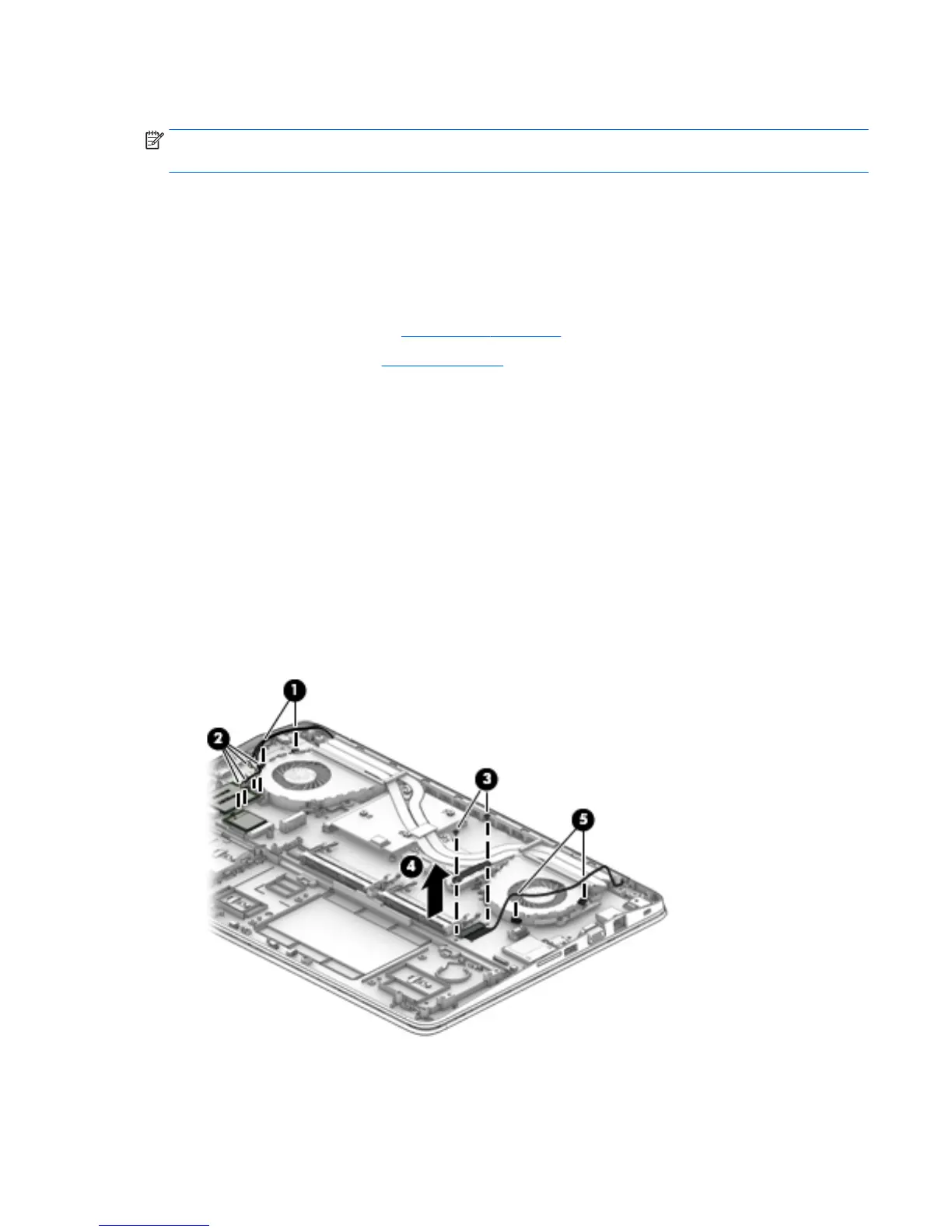
3. Remove the antenna cables from the clips in the graphics card fan (1) and disconnect the antenna cables
from the WLAN module (2).
4. Remove the two Phillips PM2.0×3.0 screws (3) that secure bracket atop the display panel cable on the
system board.
5. Remove the display panel cable bracket (4).
The display panel cable bracket is included in the Bracket Kit, spare part number 848232-001.
6. Remove the display cable from the side of the processor fan and disconnect the cable (5) from the
system board.
7. Open the computer with the display at a 90 degree angle as shown in the following image.
8. Remove the six Torx T8M2.0×3.0 screws (1) that secure the hinge cover to the computer.
Component replacement procedures 67
 Loading...