32 - English
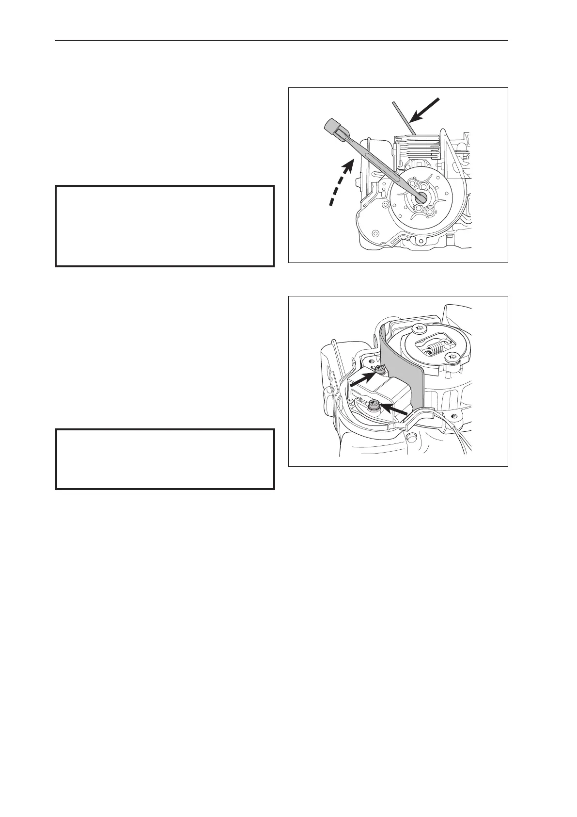
Fig 33
Fig 34
7.10 Assembling the ignition system
3
Assemble the ignition module.
Adjust the air gap. It should be 0.3 mm between
the permanent magnets in the flywheel and
the ignition module. Use the feeler gauge no.
502 51 34-02. See figure 34.
4
Route the spark plug cable through the guides on
the crankcase and the muffler’s cooling plate.
1
Check that the cast key in the flywheel and key
way in the crankshaft are undamaged.
2
Fit piston stop no. 521 54 83-01 in the spark plug
hole.
Fit the flywheel on the crankshaft. See figure 33.
NOTE!
Make sure the spark plug cable does not
contact the cylinder or the muffler.
5
Assemble other parts in the reverse order as set
out for dismantling.
NOTE!
Position the piston stop so it is clamped
between the piston crown and the
combustion chamber. Make sure that it
does not stick out into the exhaust port.
Repair Instructions
 Loading...