38 - English
Fig 51
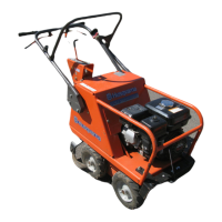
Fig 50
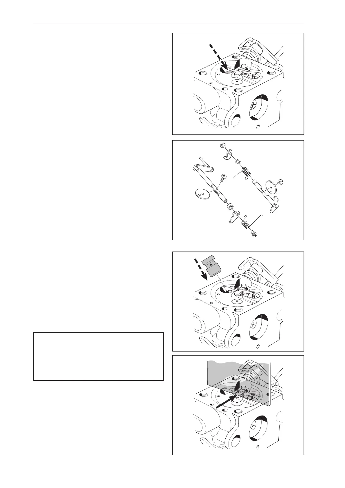
Fig 53
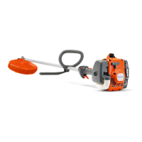
Fig 52
The blending unit
1
Press out the main jet (A) with a suitable punch.
Remember how far it is pressed into the carburettor
housing. See figure 50.
2
Remove the valves and dampers. If these
components are worn, idling is disrupted.
Always replace the valves and dampers at the
same time.
7.16 Assembling the carburettor
1
Blow all channels in the carburettor compartment
clean.
2
Press in a new main jet. Use a suitable punch and
hammer. See figure 52.
3
Fit the valves and dampers.
Tip!
Any numbers on the valves should be able to be
read from the outside.
NOTE!
Check that the valves are turned correctly and
that they close completely and tightly in the
closed position.
Use Loctite on the valve screws.
4
Fit the needle valve and the lever arm.
The lever arm should lie flush with the carburettor
housing:
• Too high setting = too much fuel.
• Too low setting = too little fuel.
See figure 53.
Repair Instructions
 Loading...