English - 51
The task of the crankshaft is to transform the reciprocating motion of the piston to rotation. This requires a
stable design withstanding immense pressure and rotational and bending strain, as well as high rotational
speed. In addition the connecting rod is exposed to large acceleration and retardation forces as it moves
between the top and bottom dead centres. This puts special demands on the bearings that must withstand
quick changes in load. Moreover, the bearing’s roller retainer must also cope with high temperatures and
friction. It is therefore extremely important when servicing to check the roller retainer for cracks, wear and
discolouration caused by overheating.
The crankshaft is journalled in the crankcase on heavy-duty ball bearings. In addition to the journalling
point for the crankshaft, the crankcase acts as a scavenging pump for the fuel/air mixture when this
is “sucked” from the carburettor and is forced into the cylinder’s combustion chamber. The crankcase
must be perfectly sealed so as not to affect this pump function. There cannot be any leakage from the
crankshaft, between the crankcase halves or between the crankcase and the cylinder.
Always replace the sealing rings and gaskets when servicing the crankcase.
7.21 Dismantling the crankcase and
crankshaft
Dismantle the following components to make the
crankcase and crankshaft accessible:
• The starter and air filter.
• The muffler with heat guard plate.
• The spark plug.
• The carburettor.
• The clutch cover and shaft.
• The cylinder and piston.
• The clutch, drive disc cup and flywheel.
1
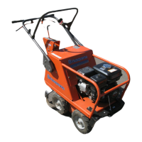
Dismantle the 3 screws holding the crankcase
halves together. See figure 67.
Fig 67
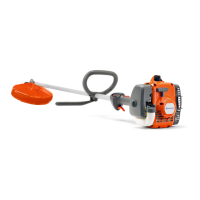
2
Separate the crankcase halves (a special tool is
not required). See figure 68.
The crankshaft has a snug fit in the crankshaft
bearing.
Fig 68
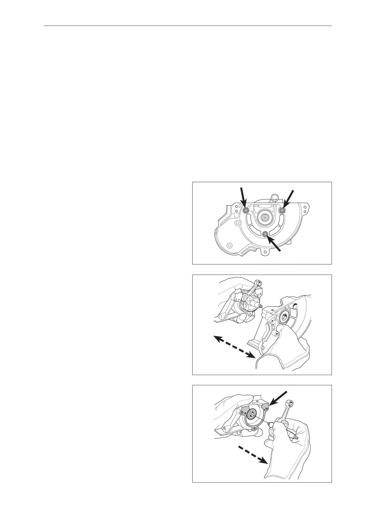
3
Lift out the crankshaft out of the clutch side’s
crankcase half (a special tool is not required).
Remove the crankcase gasket. See figure 69.
Fig 69
Crankshaft and crankcase
Crankshaft and crankcase
 Loading...