17 TUNING THE ENGINE
124
401951-10
–
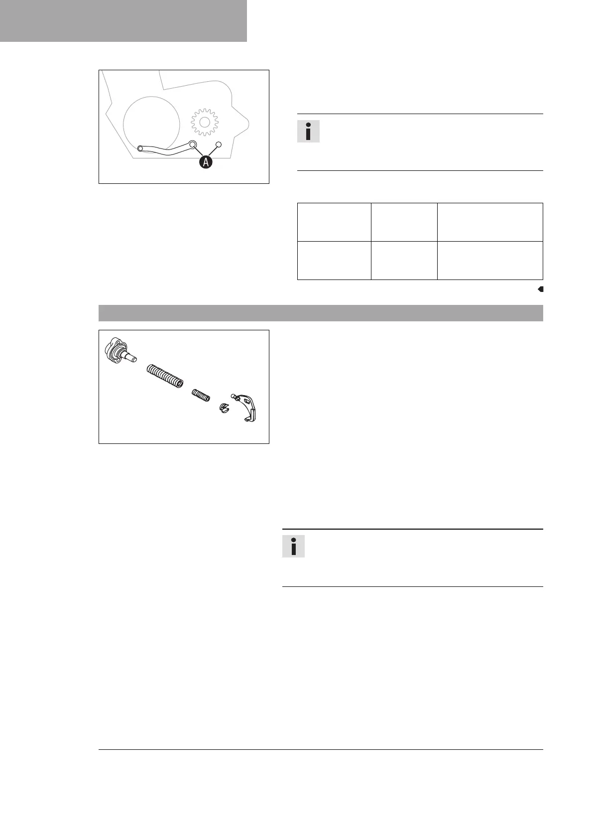
Clean gear teeth
A
of the shift lever and shift shaft.
– Mount the shift lever on the shift shaft in the required position
and engage the gearing.
Info
The range of adjustment is limited.
The shift lever must not come into contact with any
other vehicle components during the shift procedure.
–
Mount and tighten screw
1
with washers.
Guideline
Screw,
shift lever
(TX 125 EU)
M6 14 Nm (10.3 lbf ft)
Loctite
®
243™
Screw,
shift lever
(TE 150 US)
M6 14 Nm (10.3 lbf ft)
Loctite
®
243™
17.10 Engine characteristic – auxiliary spring
B00056-10
The auxiliary spring is located on the right side of the engine
below the water pump cover.
Possible states
• Auxiliary spring with green color coding – Auxiliary spring for
soft performance.
• Auxiliary spring with yellow color coding – Auxiliary spring
for more aggressive performance than with a green spring.
• Auxiliary spring with blue color coding – Auxiliary spring for
more aggressive performance than with a yellow spring.
• Auxiliary spring with red color coding – Auxiliary spring for
more aggressive performance than with a blue spring.
• Auxiliary spring without color coding – Auxiliary spring for
progressive performance (at first more aggressive than with
the red spring, then softer than with the red spring).
The engine characteristic can be influenced by different spring
strengths of auxiliary spring
1
.
Info
The auxiliary spring mounted in the as-delivered state as
well as the additionally available auxiliary springs can dif-
fer depending on model.
 Loading...