HySpeed HT2000LHF Instruction Manual c-1
6
Appendix C
INITIAL HEIGHT SENSING CONNECTIONS
NOTE: If using Command THC refer to Instruction manual # 802780
See page 3-8 for connections to power supply and IHS console. See Fig. c-1 for typical IHS connections.
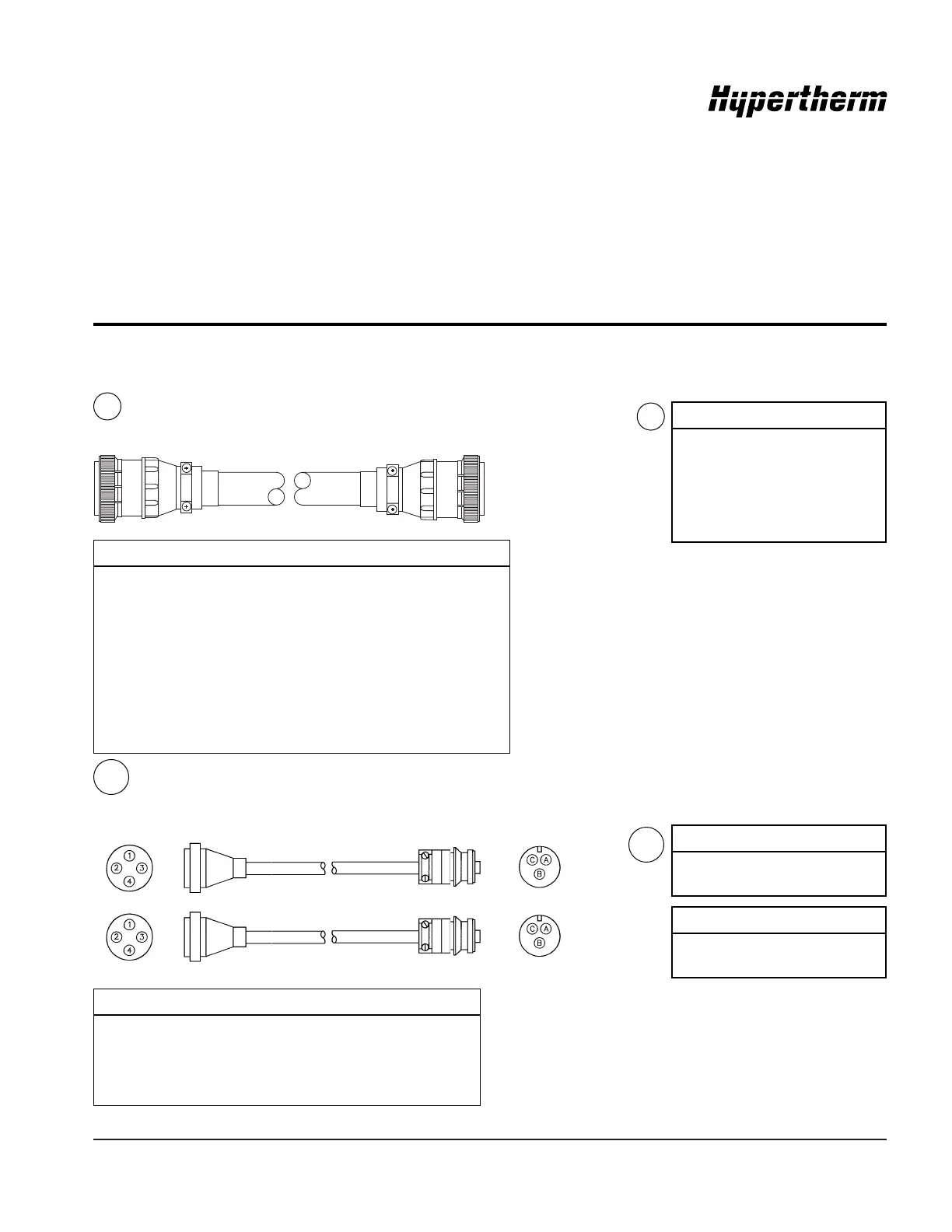
IHS Interface Cable – Power Supply to IHS
14
8X1
Power Supply End
IHS End
1X9
1X9 8X1 Color Signal
1 1 Red IHS Complete Sig
4 4 Black IHS Complete Com
8 Shield Drain
2 2 Green Upper Limit Sw Sig
5 3 Black Upper Limit Sw Com
9 5 Shield Drain
11 9 Black AC Power
14 8 White AC Power
7 Shield Drain
7 Key
8X2/8X3 8X4/8X5 Color Signal
4 A Red Power (+15 VDC)
2 B Black Common
1 C Clear Signal
3 Braid Shield
14
Part No. Length
023859 25 ft (7.6m)
023860 50 ft (15m)
023861 75 ft (23m)
023862 100 ft (30.5m)
023863 150 ft (46m)
023864 200 ft (61m)
IHS Sensor cables – IHS to Inductor Probes
The two sensor cables are components of the interconnecting leads for the inductive IHS system – see page c-4.
Part No. Length
023888 2 ft (.6 m)
023869 40 ft (12 m)
Part No. Length
023889 2 ft (.6 m)
023870 40 ft (12 m)
8X2
8X3
8X4
8X5
14A
14A
 Loading...