OPERATION
4-2 HySpeed HT2000LHF Instruction Manual
6
Gas Console
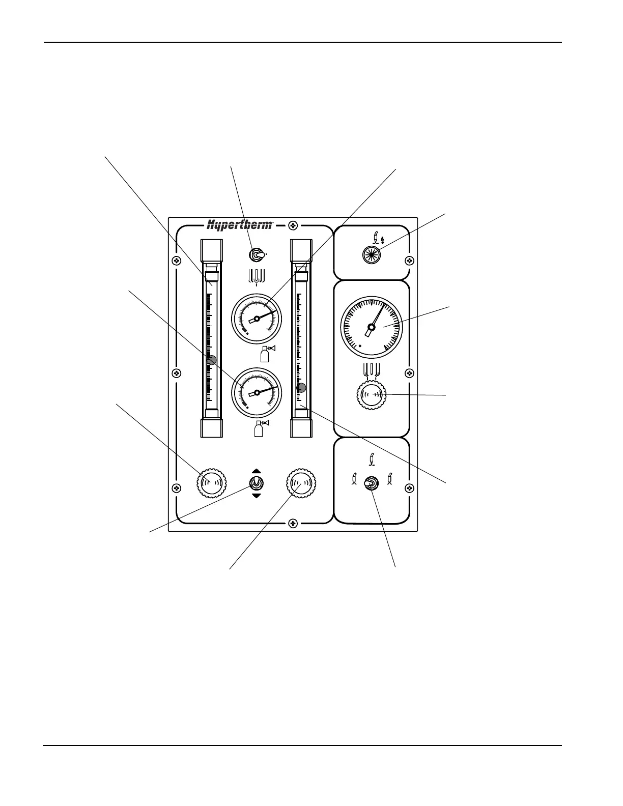
Figure 4-2 LHF Gas Console Front Panel Controls and Indicators
S2
Test Preflow – Used when setting the
plasma preflow flow rate on the flowmeter. In
this position the contactor is disabled.
Test Cut Flow – Allows the selected plasma
gas flow rate to be adjusted on the flowmeter
for cutting conditions. In this position the
contactor is disabled.
Run – Enables the contactor and the
subsequent firing of the arc after the gas
rates have been set in the Test Preflow and
Test Cut Flow positions.
LT1
Illuminates when the main
contactor closes, indicating
that DC power is being
supplied to the torch.
FM1
Indicates the flow rate % of nitrogen or air
plasma gas. Percentages are specified in the
Cut Charts.
PG1
Indicates the nitrogen or air plasma inlet
pressure. Gas inlet pressures are specified
in the Cut Charts.
FM2
Indicates the flow rate % of
oxygen plasma gas.
Oxygen flow rate percent-
age is specified in the
Cut Charts.
PG2
Indicates the oxygen plasma
inlet pressure. Gas inlet
pressures are specified in the
Cut Charts.
MV1
Adjusts flow rate % of nitrogen,
air or oxygen plasma gas while
in Test Cut Flow mode. Cut
Flow plasma gas flow rate
percentages are specified in the
Cut Charts.
S1
Selects the use of either nitrogen,
air or oxygen as the plasma cutting
gas.
MV2
Adjusts flow rate % of nitrogen,
or air plasma gas while in the
Test Preflow mode. Preflow
plasma gas flow rate percent-
ages are specified in the
Cut Charts.
MV3
Adjusts flow rate % of oxygen plasma gas
while in Test Preflow mode. Preflow
plasma gas flow rate percentages are
specified in the Cut Charts.
PG3
Indicates the shield gas
pressure at the torch.
MV4
Adjusts shield gas pressure
to the torch.
Designations
FM1-FM2 –– Flowmeters
LT1 –– Indicator Lamp
MV1-MV3 –– Motor Valve
PG1-PG3 –– Pressure Gauges
S1-S2 –– Toggle Switch
 Loading...