3. Record the bus number value, BBBB, of the IOP or IOA Direct Select Address. See SRC address
formats. Search for the bus number in HSM or the System Configuration Listing to determine which
frame or I/O tower contains the failing component. Record the frame or tower type.
4. The failing component is the FRU containing the multi-adapter bridge. Identify the system model,
tower, expansion unit, or machine type that is indicated by the location in the SAL, or by using the bus
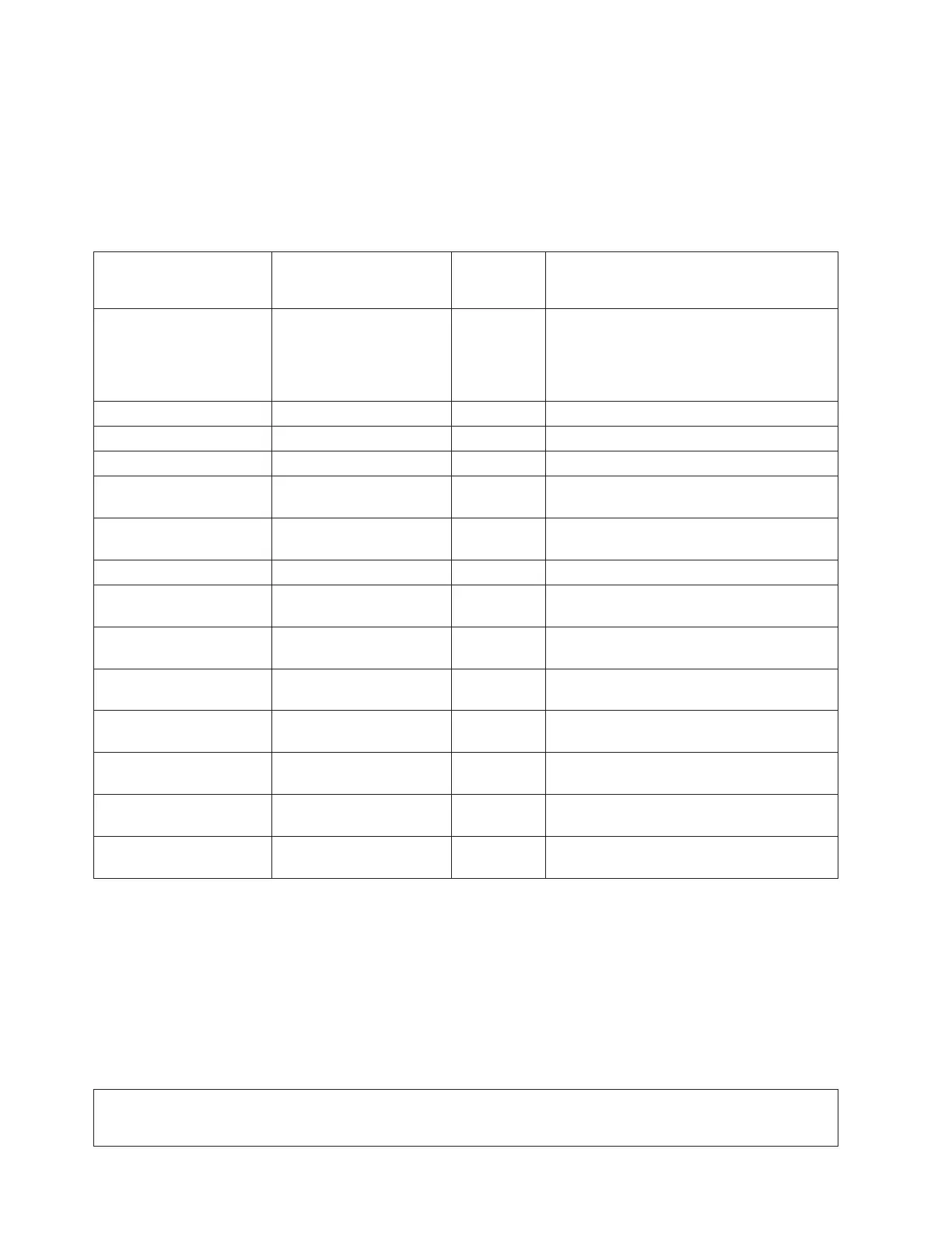
number, BBBB. Using the information provided in the table below, exchange the FRU that is indicated.
Table 1. FRU containing the multi-adapter bridge
System model, tower,
expansion unit or
machine type
Name of FRU to
exchange
FRU
position
Link to failing component service
information (CCIN, locations diagram,
remove and replace procedure).
Model 270
Record the processor
feature code (characters 5
through 8 of function 20 on
the control panel)
System unit backplane MB1 Use the Model 270 diagrams and tables by
processor feature code and follow the
Locations diagram link or the FRU positions
and failing components link for the processor
feature code.
Models 800 and 810 System unit backplane MB1 See Locations — Models 800 and 810
Model 820 System unit backplane MB1 See Locations — Model 820
Model 825 System unit backplane CB1 See Locations — Model 825
Models 830 and SB2 base
I/O tower (FC 9074)
Tower card CB1 See Locations — Models 830, SB2 system
unit with FC 9074 base I/O tower.
Models 840 and SB3 Base
I/O Tower (FC 9079)
Tower card CB1 See Locations for FC 9079 Base I/O Tower
(On Models 840, SB3 system unit).
Models 870 and 890 Tower card CB1 See Locations — Models 870 and 890.
FC 5074 Expansion I/O
Tower
Tower card CB1 See Locations — FC 5074 I/O Tower.
FC 5075 Expansion I/O
Tower
Tower card CB1 See Locations — FC 5075 I/O tower.
FC 5078, 0578 expansion
I/O unit
Tower card CB1 See Locations — FC 5078, 0578 Expansion
I/O Unit.
FC 5079 (1.8m expansion
tower)
Tower card CB1 See Locations — FC 5079 I/O tower.
FC 5088, FC 0588 PCI
Expansion Unit
Tower card CB1 See Locations — FC 5088, FC 0588
Expansion I/O Tower.
FC 5095, FC 0595 PCI
Expansion Tower
Tower card CB1 See Locations — FC 5095, FC 0595
Expansion I/O Tower.
External xSeries Server Integrated xSeries Adapter
Card
Follow the
HSL cables.
See Locations — Integrated xSeries Adapter
Card (IXA).
This ends the procedure.
MAPPWR
For use by authorized service providers.
Use this procedure to help locate power problems in the processor subsystem, I/O subsystems, or rack. If
a problem is detected, this procedure helps you isolate the problem to a failing unit. Observe the following
safety notices during service procedures.
DANGER
An electrical outlet that is not correctly wired could place hazardous voltage on metal parts of the system or
the products that attach to the system. It is the customer’s responsibility to ensure that the outlet is
correctly wired and grounded to prevent an electrical shock. (RSFTD201)
364 iSeries: iSeries Server 270, 800, 810, 820, 825, 830, 840, 870, 890, SB2, and SB3 Hardware Problem Analysis and
Isolation
 Loading...


