v For FC 5088 or FC 0588, choose from the following options:
– (With reference code 7610, 7611, 7620, 7621, 7630, 7631, 7640, 7641) replace one part at a
time:
- Air moving device (AMD) control card (see Locations - FC 5078, 0578 Expansion I/O unit for
locations and part number information)
- part CCIN 28B8 (TWRCARD)
–
(Except reference code 7610, 7611, 7620, 7621, 7630, 7631, 7640, 7641) replace - part CCIN
28B8 (TWRCARD).
v For xSeries
(TM)
Server Tower, replace the Integrated xSeries
(TM)
Adapter card. See Locations —
Integrated xSeries
(TM)
Adapter Card (IXA) for locations information, part number, and directions to
the remove and replace procedures before exchanging the part.
Note: For SRC 1xxx-8910 or 8920, ac removal is required to reset the flashing (frame indicating)
LEDs that are located on the TWRCARD.
This ends the procedure.
TWRPLNR
TWRPLNR: I/O tower PCI board.
The failing component is in the Tower Card of an FC 5074, FC 5079 (1.8m) Expansion I/O Tower, or an
FC 5078/0578 Expansion I/O Unit, or (on a Model 830, 840, SB2, SB3, or 890) a FC 9074, FC 9079, or
FC 9094 Base I/O Expansion Tower.
1. Choose from the following options:
v If you are working from the Service Action Log and a card position is listed with this failing
component, then that is where the error is located, continue with the next step in this procedure.
v Otherwise, record the bus number value, BBBB, in word 7 of the SRC, see “Breaking down the
SRC” on page 63 for help in determining the bus number. Search for the bus number in HSM or the
System Configuration Listing to determine which tower contains the failing component. Record the
tower type.
2.
Use the feature code of the tower or expansion unit and the table below to determine the service
information for the failing component.
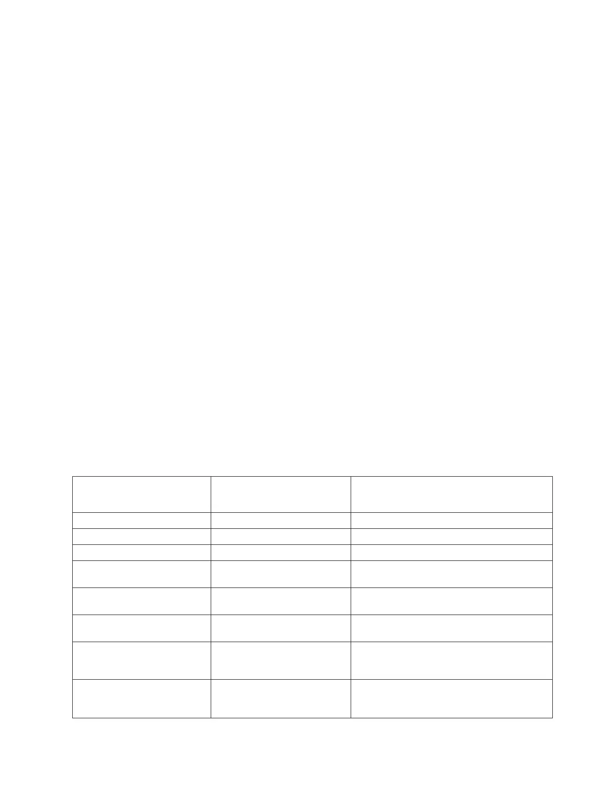
Table 1. Failing Component Service Information table for symbolic FRU TWRPLNR
System model, Tower,
Expansion unit, or Machine
type
Name of FRU to exchange Link to Failing Component Service
Information. (CCIN, PN, Remove and replace
procedure)
FC 5074 Expansion I/O Tower Tower card Locations — FC 5074 Expansion I/O Tower
FC 5078/0578 Epansion I/O Unit Tower card Locations — FC 5078, 0578 Expansion I/O Unit
FC 5079 (1.8m Expansion Unit) Tower card Locations — FC 5079 Expansion I/O Tower
FC 5088 or FC 0588 Expansion
I/O Unit
Tower card Locations — FC 5088, FC 0588 Expansion I/O
Unit
FC 5094 Expansion I/O Tower Tower card Locations — FC 5094, FC 0594 Expansion I/O
Tower
Model 890 System Unit with FC
9094 Base I/O Tower.
Tower card Locations — Model 890 with an FC 9094 Base
I/O Tower
Models 830 and/SB3 System
Unit with FC 9074 Base I/O
Tower
Tower card Locations — Models 830, SB2 System Unit with
FC 9074 Base I/O Tower
Models 840/SB3 System Unit
with Processor Tower and FC
9079 Base I/O Tower
Tower card Locations Models 840/SB3 System Unit with
Processor Tower and FC 9079 Base I/O Tower
Analyze hardware problems 473
 Loading...


