v Do not remove the first microprocessor from the system board when you install
the second microprocessor.
v When you install the second microprocessor, you must also install additional
memory and the fourth and sixth fans. See “Installing a memory module” on
page 34 for details about the memory installation sequence.
v To ensure proper server operation when you install an additional
microprocessor, use microprocessors that have the same QuickPath Interconnect
(QPI) link speed, integrated memory controller frequency, core frequency, power
segment, internal cache size, and type.
v Mixing microprocessors of different stepping levels within the same server
model is supported.
v When mixing microprocessors with different stepping levels within the same
server model, you do not have to install the microprocessor with lowest
stepping level and features in microprocessor socket 1.
v Both microprocessor voltage regulator modules are integrated on the system
board.
v Read the documentation that comes with the microprocessor, so that you can
determine whether you have to update the server firmware. To download the
latest level of the server firmware and other code updates for your server, go to
http://www.ibm.com/supportportal/.
v If the thermal-grease protective cover (for example, a plastic cap or tape liner) is
removed from the heat sink, do not touch the thermal grease on the bottom of
the heat sink or set down the heat sink. For details, see Thermal grease.
Note: Removing the heat sink from the microprocessor destroys the even
distribution of the thermal grease and requires replacing the thermal grease.
v To order an additional optional microprocessor, contact your IBM marketing
representative or authorized reseller.
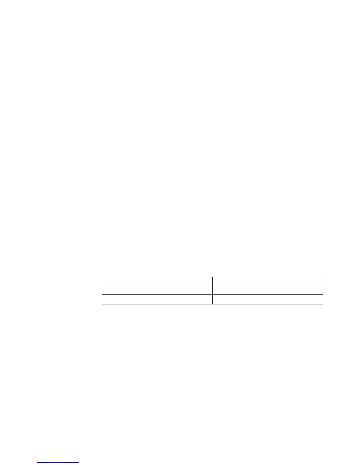
v The following table shows the DIMM connectors on the system board and the
DIMM connectors that are associated with each microprocessor:
Table 9. DIMM connectors associated with each microprocessor
Microprocessor DIMM connectors
Microprocessor socket 1 1 through 6
Microprocessor socket 2 7 through 12
To install an additional microprocessor and heat sink, complete the following steps:
1. Read the safety information that begins on page Safety and “Installation
guidelines” on page 30.
2. Turn off the server (see “Turning off the server” on page 21) and all attached
peripheral devices. Disconnect all power cords; then, disconnect all external
cables from the server.
Attention: When you handle static-sensitive devices, take precautions to
avoid damage from static electricity. For details about handling these devices,
see “Handling static-sensitive devices” on page 32.
3. Remove the top cover (see “Removing the server top cover” on page 33).
4. Remove the air baffle (see “Removing the air baffle” on page 33).
5. Locate microprocessor socket 2 on the system board.
6. Remove the heat-sink filler, if one is present.
7. Open the microprocessor socket release lever and retainer.
Chapter 2. Installing optional devices 51
 Loading...