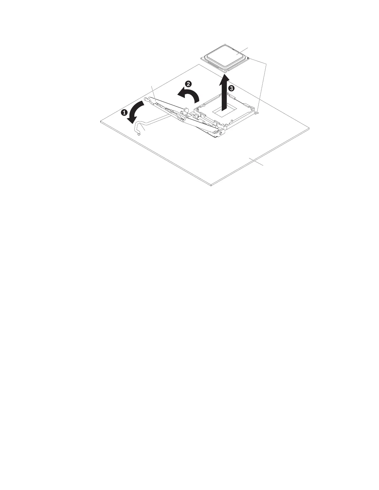
8. Open the microprocessor bracket frame by lifting up the tab on the top edge.
9. Carefully lift the microprocessor straight up and out of the socket, and place it
on a static-protective surface.
10. If you are instructed to return the microprocessor and heat sink, follow all
packaging instructions, and use any packaging materials for shipping that are
supplied to you.
To remove the microprocessor and heat sink on the 5U server model with
hot-swap power supplies, complete the following steps. For 4U server models with
non-hot-swap power supplies, please see the above sub-section.
1. Read the safety information in “Safety” on page vii and “Installation
guidelines” on page 35.
2. Turn off the server and all attached devices; then, disconnect all power cords
and external cables.
3. Unlock and remove the side cover (see “Removing the side cover” on page
38).
4. Carefully turn the server on its side so that it is lying flat, with the system
board facing up.
Attention: Do not allow the server to fall over.
5. Rotate the rear adapter-retention bracket to the open (unlocked) position.
6. Remove the heat sink from the microprocessor:
CAUTION:
The heat sink may become very hot during normal operation. Allow time
for the heat sink to cool down before you touch it.
a. Loosen the screws and alternate among the screws until they break the
seal with the microprocessor.
b. Press firmly on the captive screws and loosen them with a screwdriver.
c. Use your fingers to gently pull the heat sink from the microprocessor.
Microprocessor
Alignment
marks
Microprocessor
bracket frame
Microprocessor
release lever
System board
Figure 220. Microprocessor socket levers and retainer disengagement for 4U server model
with non-hot-swap power supplies
302 System x3100 M5 Type 5457: Installation and Service Guide
 Loading...