3
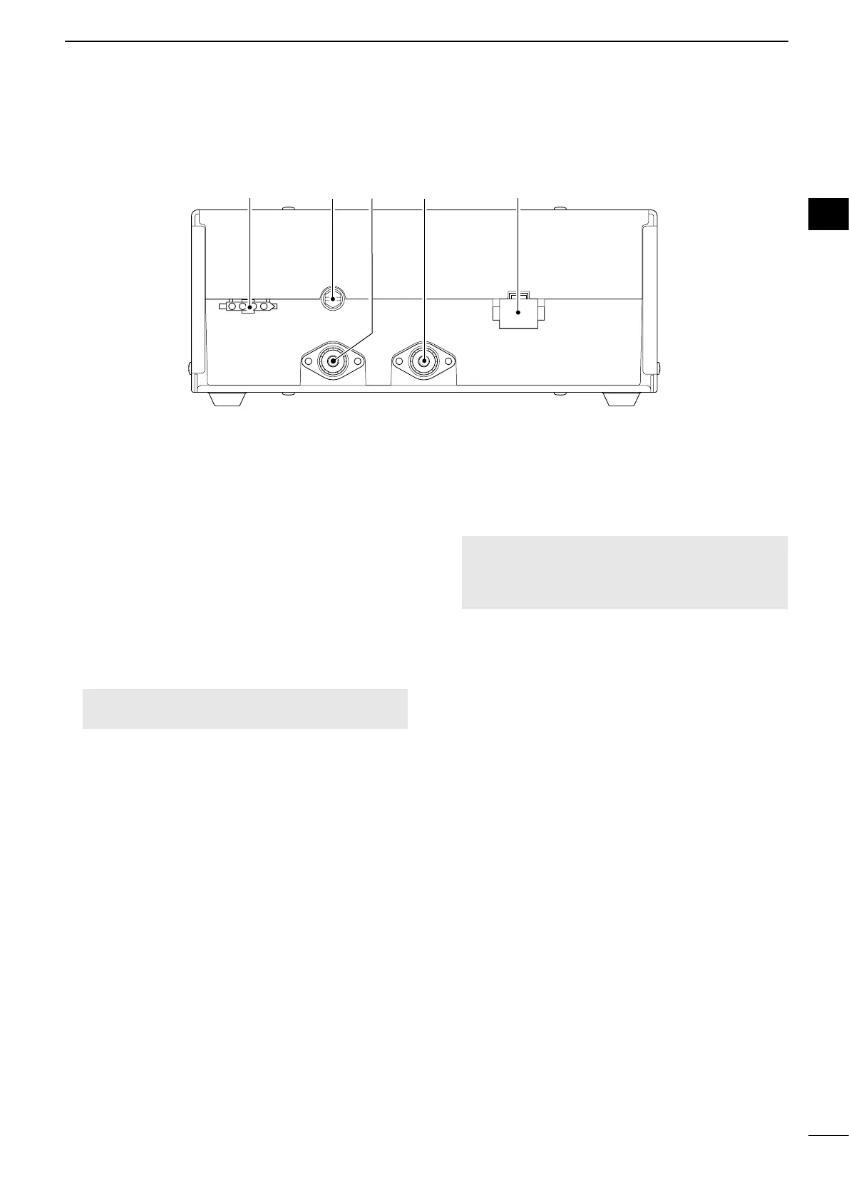
PANEL DESCRIPTION
2
2
1TUNER CONTROL SOCKET (pp. 70, 71, 78)
Connects to the control cable of the supplied
AT-140 . A female
connector kit is supplied to connect the AT-140.
2GROUND TERMINAL (p. 71)
Connects to the vessel’s ground.
3ANTENNA CONNECTOR (p. 70, 71)
Connects to a dipole antenna, or an automatic
transmitting any calls and receiving any calls, other
than Distress calls.
R WARNING! NEVER connect the antenna
directly to this connector.
4DSC ANTENNA CONNECTOR (p. 70, 71)
This antenna is used for receiving Distress calls.
NOTE: To receive a Distress call, BE SURE
antenna connector. Otherwise, you cannot receive
any Distress calls.
5DC POWER SOCKET (p. 70, 78)
Connects to 13.6 V DC through the supplied DC
power cable.
■ Main unit rear panel
1 2 3 4 5
 Loading...