3-2
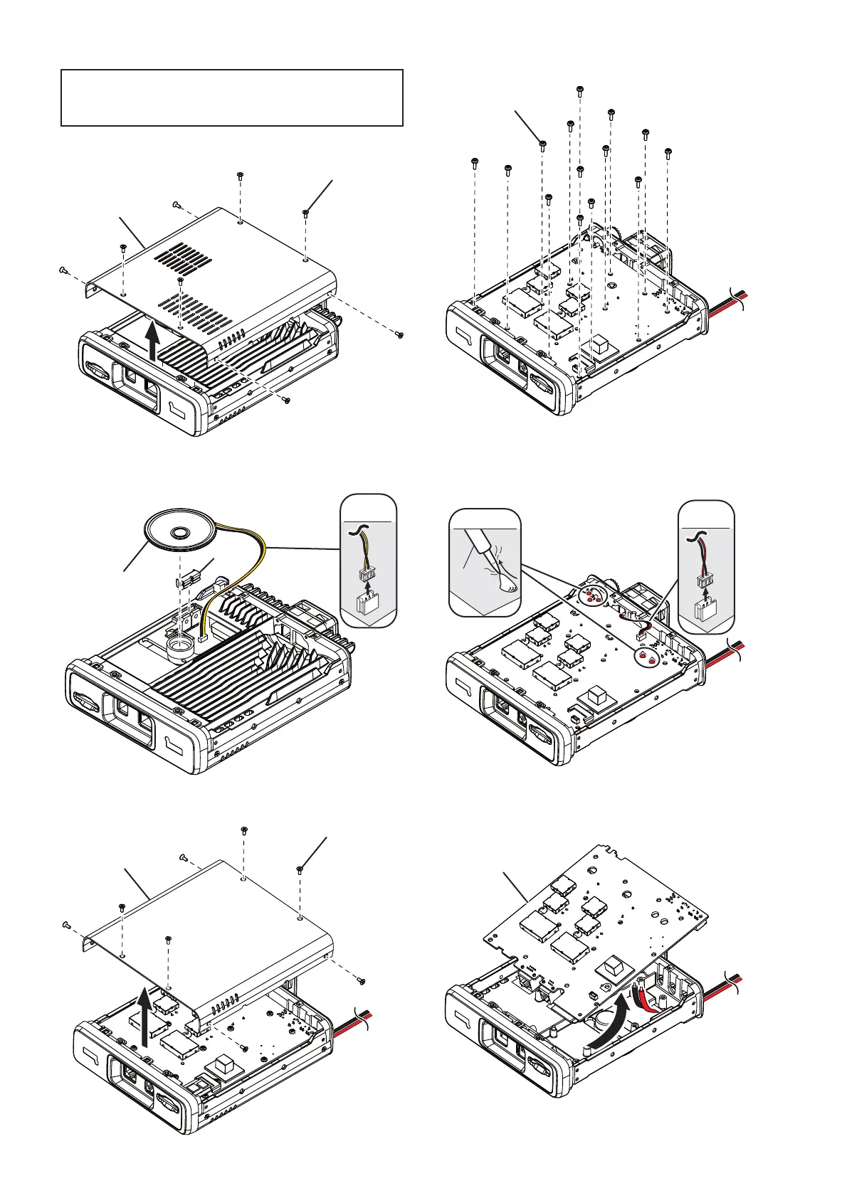
1) Remove eight screws from the top cover.
2) Remove the clip and disconnect the speaker cable.
3) Remove eight screws from the bottom cover.
Bottom cover
Eight screws
Speaker
Clip
SPEAKER
CABLE
Bottom cover
Eight screws
14 screws
FAN
CABLE
UNSOLDER
Solder
remover
MAIN UNIT
4) Remove total of 14 screws from the MAIN UNIT.
5) Disconnect the cooling fan cable, and unsolder fi ve
points (at the antenna connector and the DC cable).
6) Remove the MAIN UNIT from the chassis in the di-
rection of the arrow.
(Continued on the right above.)
Before disassembling:
REMOVE the SD card if inserted. Otherwise the MAIN
UNIT and chassis cannot be separated.
M Removing the MAIN UNIT from the chassis.

 Loading...


