5-1
SECTION 5
ADJUSTMENT PROCEDURE
M CONNECTION
5-1 PREPARATION
M REQUIRED TEST EQUIPMENT
EQUIPMENT GRADE AND RANGE EQUIPMENT GRADE AND RANGE
DC power supply
Output voltage: 13.8 V DC
Current capacity: More than 20 A
JIG cable
Modifi ed 8-pin modular jack
(See the illustration shown below.)
Audio generator
Frequency range: 300–3000 Hz
Output level: 1–500 mV
RF power meter
(terminated type)
Measuring range: 1–100 W
Frequency range: 100–600 MHz
Impedance: 50
SWR: Less than 1.2 : 1
Standard signal
generator (SSG)
Frequency range: 0.1–600 MHz
Output level: –20 to +90 dBµ
(–127 to –17 dBm)
Frequency counter
Frequency range: 0.1–600 MHz
Frequency accuracy: ±1 ppm or better
Sensitivity: 100 mV or better
AC millivoltmeter Measuring range: 10 mV to 10 V
Terminator
Impedance: 50
Capacity: More than 100 W
Modulation
Analyzer
Frequency range: 30–600 MHz
Measuring range: DC to ±10 kHz
Attenuator
Power attenuation: 50 dB
Capacity: More than 100 W
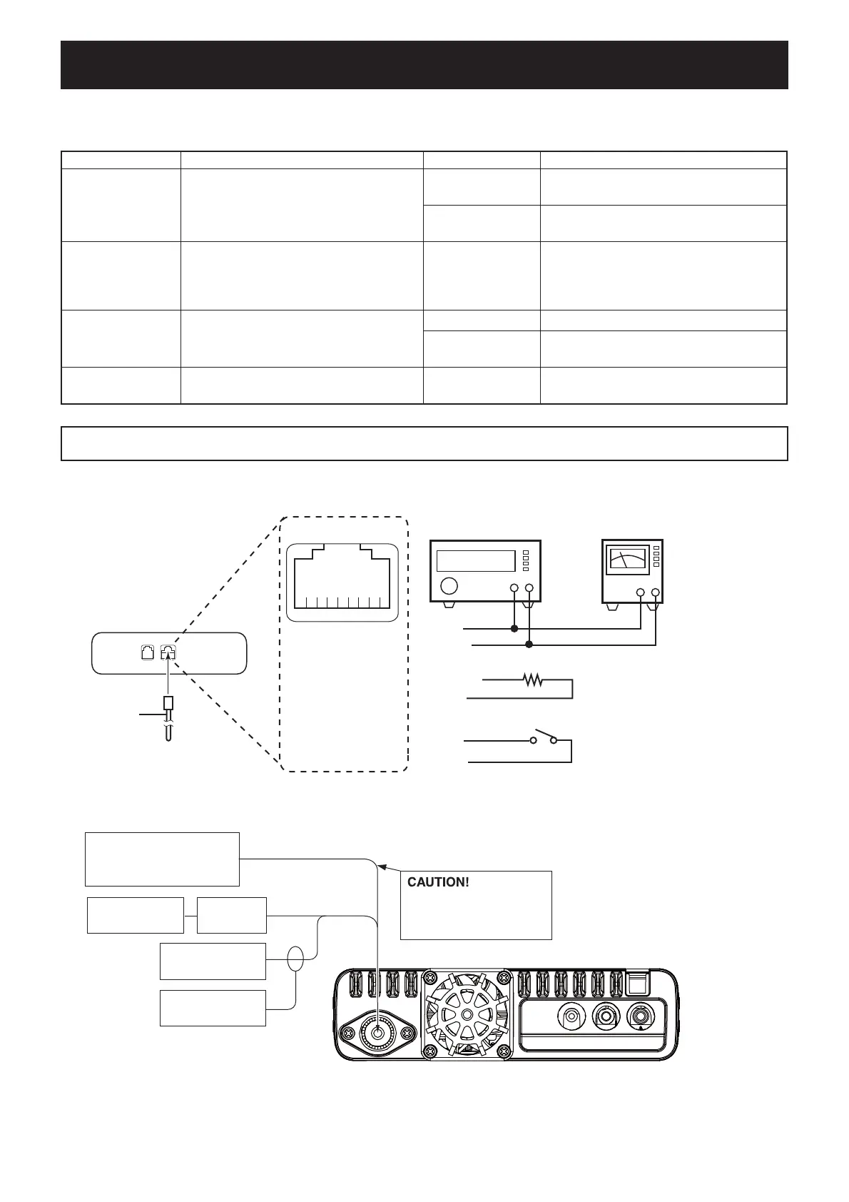
M
JIG CABLE
8-pin modular jack
q
i
u
ytr e
w
q
w
e
r
t
y
u
i
8V
MICU/D
EXTMIC
PTT
MICE
MIC
GND
MICIN
y (MIC)
w (MICU/D)
u (GND)
r (PTT)
u (GND)
t (MICE)
AUDIO GENERATOR
(300–3000 Hz/1–500 mV)
+−
22 kΩ
[PTT]
+−
AC MILLIVOLT METER
(10 mV to 10 V)
JIG cable
To the MICROPHONE CONNECTOR
ID-5100A/E (Rear view)
FM
deviation meter
to the antenna connector
Attenuator
40 dB
RF power meter
0.1–100 W/50 Ω
Frequency
counter
Standard signal generator
–20 to 90 dBµ
(–127 dBm to –17 dBm)
DO NOT transmit while
an SSG is connected to
the antenna connector.
CAUTION!:
SAVE the originally programmed contents
(Memory channel contents, set mode settings, and so on.),
before starting
adjustment. When all adjustments are completed, these contents in the transceiver may be cleared.

 Loading...


