4-2
1ST IF CIRCUITS (MAIN UNIT)
• Band A
The RX signal from the RF circuit is applied to the 1st mixer
(IC125) and mixed with the 1st LO signal, resulting in the
38.85 MHz 1st IF signal. The converted signal is passed
through the 1st IF fi lter (FI105), and then applied to the 1st
IF AMP (Q138). The amplifi ed signal is applied to the 2nd IF
circuit, through the limiter (D114).
2ND IF CIRCUITS (MAIN UNIT)
• Band A
The 1st IF signal from the 1st IF circuit is applied to the IF IC
(IC121, pin 20), which contains the 2nd IF AMP, 2nd mixer,
FM demodulator, and so on.
The 1st IF signal is mixed with the 38.4 MHz 2nd LO signal,
resulting in the 450 kHz 2nd IF signal. The converted signal
is passed through the external 2nd IF fi lter (FM mode: FI103,
FM-N or DV mode: FI102) to remove sideband noise.
While operating in the FM or AM mode, the fi ltered signal is
amplifi ed by the 2nd IF AMP, and then demodulated by the
internal demodulator circuit. The demodulated signal is ap-
plied to the RX AF circuit, through the RX mode SW (IC119),
AF fi lter (Q113 and Q140) and AF SW (IC111).
While operating in the DV mode, the fi ltered signal is ampli-
fi ed by the 2nd IF AMP, and then demodulated by the inter-
nal demodulator circuit. The demodulated signal is applied
to the digital demodulation circuit, through the RX mode SW
(IC119) and buffer AMP (IC117).
IF
AMP
BPF
XTAL
RIF
1st LO
Band B
46.35MHz
Q137/
D115/D117
FI104
2nd IF
circuit
IC124
LIMITER
D113
IF
AMP
BPF
XTAL
LIF
1st LO
Band A
38.85MHz
Q138/
D116/D118
2nd IF
circuit
FI105
IC125
LIMITER
D114
BUFF
BPF
CERAMIC
BPF
CERAMIC
X3
DET OUT
SELECT
AF
DIGI/AN
AFMUTE
FIL
IF IC
FM
FM/AM
DV
Digital
demodulation
Cricut
RX AF
Cricut
AM
Band A
38.4MHz
SELECTOR
WIDE/NARROW
12.8MHz
X200
Q200
IC111 Q113/Q140
IC117 IC119 IC121
Q122/Q124/Q142
Q128/D107/D108
D111/D112
FI102 FI103
X102
BPF
CERAMIC
BPF
CERAMIC
BUFF
X3
DET OUT
AFMUTE
FIL
IF IC
AF
WIDE/NARROW
DIGI/AN
SELECT
SELECTOR
15.3MHz
AM
FM
FM/AM
DV
Digital
demodulation
Cricut
RX AF
Cricut
Band B
45.9MHz
X201
Q220
IC111
Q112/Q139
IC117 IC120IC119
Q121/Q123/Q141
Q127/D105/D106
D109/D110
FI100 FI101
X101
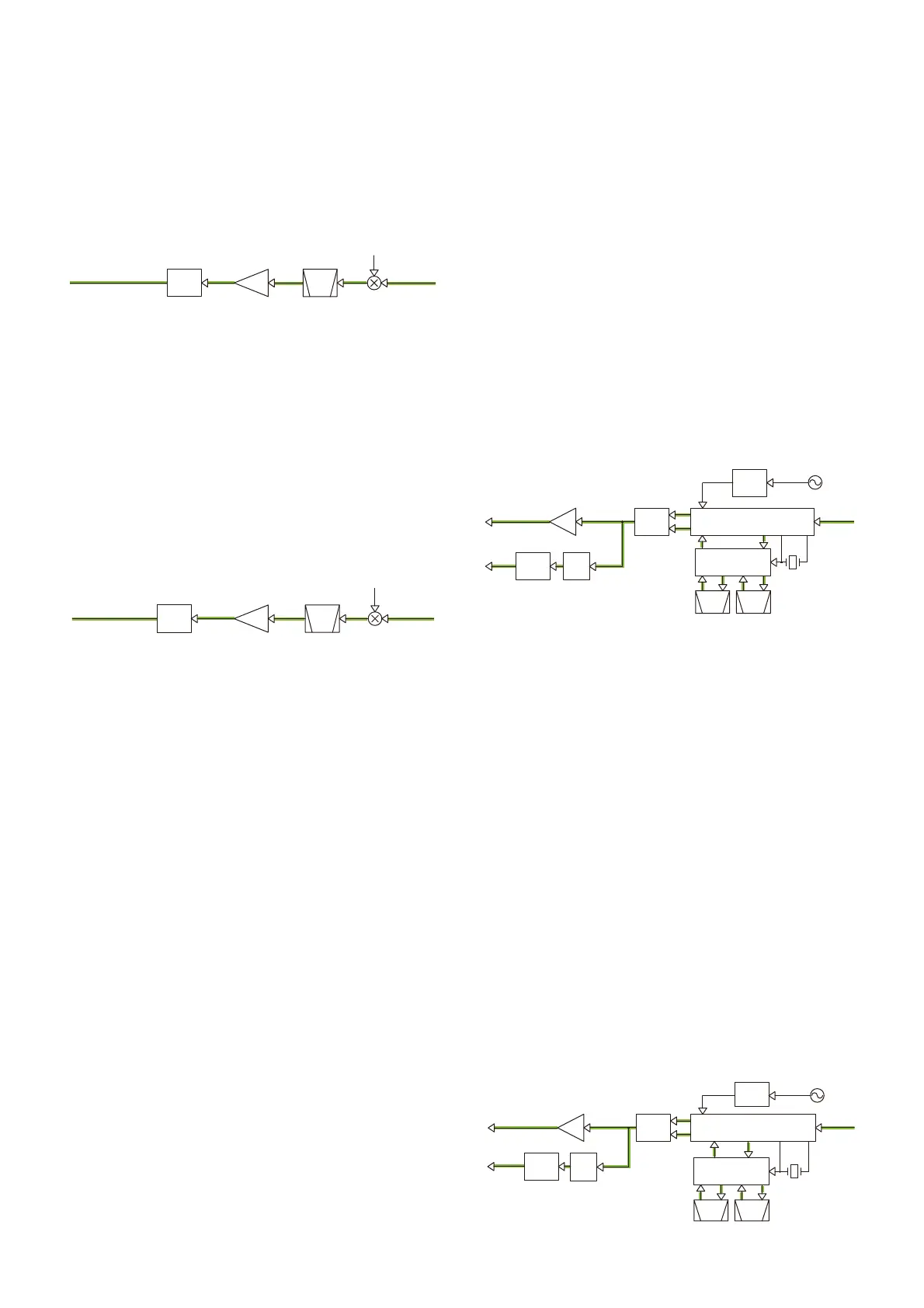
• 1ST IF CIRCUITS (Band B)
• 1ST IF CIRCUITS (Band A)
• 2ND IF CIRCUITS (Band A)
• 2ND IF CIRCUITS (Band B)
• Band B
The 1st IF signal from the 1st IF circuit is applied to the IF IC
(IC120, pin 20), which contains the 2nd IF AMP, 2nd mixer,
FM demodulator, and so on.
The 1st IF signal is mixed with the 45.9 MHz 2nd LO signal,
resulting in the 450 kHz 2nd IF signal. The converted signal
is passed through the external 2nd IF fi lter (FM mode: FI101,
FM-N or DV mode: FI100) to remove sideband noise.
While operating in the FM or AM mode, the fi ltered signal is
amplifi ed by the 2nd IF AMP, and then demodulated by the
internal demodulator circuit. The demodulated signal is ap-
plied to the RX AF circuit, through the RX mode SW (IC119),
AF fi lter (Q112 and Q139) and AF SW (IC111).
While operating in the DV mode, the fi ltered signal is ampli-
fi ed by the 2nd IF AMP, and then demodulated by the inter-
nal demodulator circuit. The demodulated signal is applied
to the digital demodulation circuit, through the RX mode SW
(IC119) and buffer AMP (IC117).
• Band B
The RX signal from the RF circuit is applied to the 1st mixer
(IC124) and mixed with the 1st LO signal, resulting in the
46.35 MHz 1st IF signal. The converted signal is passed
through the 1st IF fi lter (FI104), and then applied to the 1st
IF AMP (Q137). The amplifi ed signal is applied to the 2nd IF
circuit, through the limiter (D113).

 Loading...


