MD380 User Manual Desc
ription of Function Codes
- 237 -
Group A6: AI Curve Setting
Function Code Name Setting Range Default
A6-00 AI curve 4 minimum input -10.00 V to A6-02 0.00 V
A6-01
Corresponding setting of AI
curve 4 minimum input
-100.0% to 100.0% 0.0%
A6-02 $,FXUYHLQÀH[LRQLQSXW A6-00 to A6-04 3.00 V
A6-03
Corresponding setting of AI
FXUYHLQÀH[LRQLQSXW
-100.0% to 100.0% 30.0%
A6-04 $,FXUYHLQÀH[LRQLQSXW A6-02 to A6-06 6.00 V
A6-05
Corresponding setting of AI
FXUYHLQÀH[LRQLQSXW
-100.0% to 100.0% 60.0%
A6-06 AI curve 4 maximum input A6-06 to 10.00 V 10.00 V
A6-07
Corresponding setting of AI
curve 4 maximum input
-100.0% to 100.0% 100.0%
A6-08 AI curve 5 minimum input -10.00 V to A6-10 0.00 V
A6-09
Corresponding setting of AI
curve 5 minimum input
-100.0% to 100.0% 0.0%
A6-10 $,FXUYHLQÀH[LRQLQSXW A6-08 to A6-12 3.00 V
A6-11
Corresponding setting of AI
FXUYHLQÀH[LRQLQSXW
--100.0% to 100.0% 30.0%
A6-12 $,FXUYHLQÀH[LRQLQSXW A6-10 to A6-14 6.00 V
A6-13
Corresponding setting of AI
FXUYHLQÀH[LRQLQSXW
-100.0% to 100.0% 60.0%
A6-14 AI curve 5 maximum input A6-14 to 10.00 V 10.00 V
A6-15
Corresponding setting of AI
curve 5 maximum input
-100.0% to 100.0% 100.0%
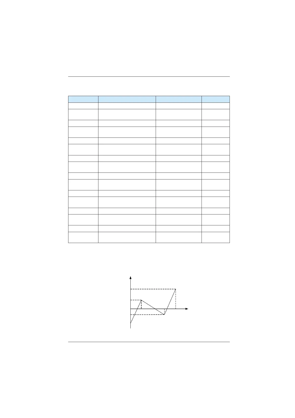
The function of curve 4 and curve 5 is similar to that curve 1 to curve 3, but curve 1 to
FXUYHDUHOLQHVDQGFXUYHDQGFXUYHDUHSRLQWFXUYHVLPSOHPHQWLQJPRUHÀH[LEOH
corresponding relationship. The schematic diagram of curve 4 and curve 5 is shown in the
IROORZLQJ¿JXUH
Figure 6-35 Schematic diagram curve 4 and curve 5
AI corresponding setting
Corresponding setting
of AI max. input
Corresponding setting of
AI curve inflexion 1 input
0 V (0 mA)
Corresponding setting of
AI curve inflexion 2 input
Corresponding setting
of AI min. input
AI curve
inflexion 1
AI curve
inflexion 2
AI input
voltage
10 V (20 mA)
efesotomasyon.com
 Loading...