Chapter 4 Operation and Trial Running
- 34 -
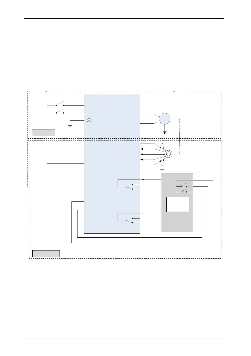
4.4.2 Distance Control Mode
1. The encoder needs to be installed for this mode. The controller judges the door position
based on the encoder signals. The door width pulses need to be identied at rst-time running.
The controller decelerates and judges door open/close limit based on the door open/close
curve.
The following gure takes Inovance elevator control system to describe wiring of the relevant
signals.
Figure 4-13 Typical system wiring for distance control
Single
-phase
220
VAC
power supply
COM
DI
1
DI2
DI
3
DI4
Input common
U
V
W
L
N
TA
1
TC
1
TB1
TA
3
TC
3
TB
3
NICE
900
Main circuit
Control circuit
DI
5
DI6
DI7
DI8
Door close
input signal
Door open
input signal
F9-05 = 1
F9-06 = 2
F9-09 = 2
F9-11 = 1
X5
Door close
limit
P24
X
3
Door open
limit
B1
B2
BM
Door open output
Door close output
Output common
Input
common
M
Door motor
Encoder
+24
V
COM
PGA
PGB
PGZ
Shield
grounded
Car top
board
MCTC-
CTB
Function
code setting
2. Check the encoder.
The pulse signal from the encoder is critical to accurate control of the system. Before
commissioning, check the following items carefully:
1) The encoder is installed reliably with correct wiring.
2) The signal cable and strong-current circuit of the encoder are laid in different ducts to
prevent interference.
3) The encoder cable is preferably directly connected to the controller. If the cable is not long
enough and an extension cable is required, the extension cable must be a shielded cable
and preferably welded to the original encoder cable by using the soldering iron.
 Loading...