Case Temperature Reference Metrology
Thermal and Mechanical Design Guidelines 105
D.5.4 Cleaning and Completion of Thermocouple
Installation
33. Remove the device from the solder station and continue to monitor IHS
Temperature with a handheld meter. Place the device under the microscope and
remove the three pieces of Kapton* tape with Tweezers, keeping the longest for
re-use.
34. Straighten the wire and work the wire in to the groove. Bend the thermocouple
over the IHS. Replace the long piece of Kapton* tape at the edge of the IHS.
Note: The wire needs to be straight so it doesn’t sit above the IHS surface at anytime (see
Figure 7-31).
Figure 7-31. Thermocouple placed into groove
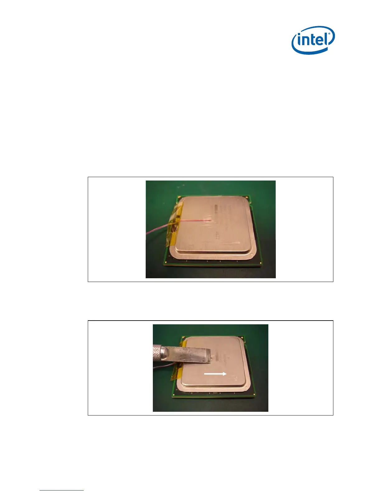
35. Using a blade carefully shave the excess solder above the IHS surface. Only shave
in one direction until solder is flush with the groove surface (see Figure 7-32).
Figure 7-32. Removing Excess Solder
Note: Take usual precautions when using open blades
 Loading...