Legacy Fan Speed Control
Thermal and Mechanical Design Guidelines 119
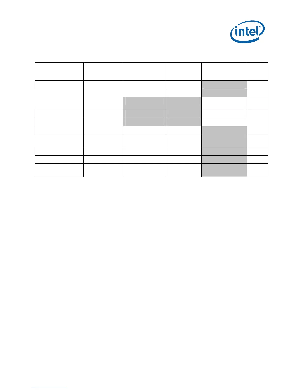
Table 7-5. Balanced Technology Extended (BTX) Fan Speed Control Settings
Parameter Classification Processor
Thermal Sensor
System
Ambient
Sensor
PWM Output Notes
T
HIGH
Required T
CONTROL
54 °C 3,5,9
T
LOW
Required T
CONTROL
– 7 °C 47 °C 3,5,9
Minimum PWM Duty
Cycle
Required PWM 1 (TMA) –
20%
PWM Frequency Required 21-28 kHz 1
Spin Up Time Suggested 250 – ~ 500 ms 2, 7
T
AVERAGING
Suggested 4.0 sec 4.0 sec 3, 7
When T
SENSOR
< T
LOW
Suggested Minimum PWM% Minimum
PWM%
All Fans On Suggested T
CONTROL
+ 3 °C 65 °C
Hysteresis Suggested 2 °C 4 °C
Offset Required Thermal Diode
Correction Factor
8,9
NOTES:
1. A PWM frequency of 25 kHz is the design target for the reference and for the Intel
®
Boxed Processor and BTX reference design.
2. Use the lowest time available in this range for the device selected.
3. T
AVERAGING
= represents the amount of delay time before responding to the temperature
change, defined in fan speed control device (sometimes called ramp range control or
spike smoothing). Select the lowest setting available close to 4.0 seconds by the fan
speed control device.
4. The Fan Speed Controller, or Health Monitor Component, takes the result of the two fan
speed ramps (processor and system) and drives the TMA fan to the highest resulting
PWM duty cycle (%).
5. For BTX systems a second thermal sensor is recommended to capture chassis ambient
for more detail see Appendix F.
6. To ensure compliance with the thermal specification, thermal profile and usage of the
T
SENSOR
for fan speed control these setting should not be user configurable.
7. If this function is present on the device, it must be enabled.
8. If present in the FSC device, the Thermal Diode Correction Factor should be input to
this register.
9. If the FSC device does not have a means to input a fixed temperature offset then:
T
HIGH
= T
CONTROL
+ Thermal Diode Correction Factor and
T
LOW
= T
CONTROL
+ Thermal Diode Correction Factor.
Note: The fan speed component vendors provide libraries that are used by the BIOS writer
to program the component registers with the parameters listed above. Consult the
appropriate vendor datasheet for detailed information on programming their
component.
§
 Loading...