EasyManua.ls Logo

Intel E1400 - Celeron 2.0GHz 800MHz 512KB Socket 775 Dual-Core CPU User Manual

Intel E1400 - Celeron 2.0GHz 800MHz 512KB Socket 775 Dual-Core CPU
148 pages
To Next Page IconTo Next Page
To Previous Page IconTo Previous Page
Page #113 background image
Legacy Fan Speed Control
Thermal and Mechanical Design Guidelines 113
Figure 7-41. Temperature Range = 5 °C
0
500
1000
1500
2000
2500
3000
3500
Time (s)
40
45
50
55
60
65
70
75
80
Fan RPM Tdiode Tcontrol Tlow
An alternate would be to consider a slightly larger value such as T
RANGE
= 10 °C. In
this case the design is trading off the acoustic margin for thermal margin.
There is increased granularity in the fan speeds.
Fan speed oscillation are significantly reduced
Maximum fan speed is lower
The rate of change of
CA
vs. RPM is an exponential curve with a larger decrease at
the beginning of the fan acceleration than as the maximum speed is approached. By
having the fan start to accelerate at a lower T
SENSOR
reading the thermal solution can
keep up with rate of change in processor power. The rate of change in acoustics (dBA)
is more linear with RPM. When comparing these two metrics the choice of a larger
T
RANGE
value becomes a more acceptable trade off. Figure 7-42 graphs the system at
the same conditions as in Figure 7-41 but T
RANGE
= 10 °C.

Table of Contents

Question and Answer IconNeed help?

Do you have a question about the Intel E1400 - Celeron 2.0GHz 800MHz 512KB Socket 775 Dual-Core CPU and is the answer not in the manual?

Intel E1400 - Celeron 2.0GHz 800MHz 512KB Socket 775 Dual-Core CPU Specifications

General IconGeneral
BrandIntel
ModelE1400 - Celeron 2.0GHz 800MHz 512KB Socket 775 Dual-Core CPU
CategoryComputer Hardware
LanguageEnglish

Summary

Introduction

1.1 Document Goals and Scope

Outlines the purpose and boundaries of the thermal design guide.

Processor Thermal/Mechanical Information

2.1 Mechanical Requirements

Details physical and mechanical specifications for processor packages and heatsink attachments.

2.2 Thermal Requirements

Defines processor thermal limits, including thermal profile and TCONTROL.

2.3 Heatsink Design Considerations

Discusses key parameters for designing effective heatsinks.

Thermal Metrology

3.1 Characterizing Cooling Performance Requirements

Explains thermal characterization parameters (psi) for evaluating cooling solutions.

3.4 Processor Case Temperature Measurement Guidelines

Details procedures for measuring processor case temperature (TC).

Thermal Management Logic and Thermal Monitor Feature

4.2 Thermal Monitor Implementation

Describes the components and functionality of the processor's thermal monitor.

Balanced Technology Extended (BTX) Thermal/Mechanical Design Information

5.1 Overview of the Balanced Technology Extended (BTX) Reference Design

Introduces the BTX reference design and its compliance.

5.2 Environmental Reliability Testing

Details testing for structural reliability, including vibration and shock.

5.4 Safety Requirements

Specifies safety standards for heatsink and attachment assemblies.

5.6 Preload and TMA Stiffness

Discusses preload requirements and stiffness for BTX platforms.

ATX Thermal/Mechanical Design Information

6.1 ATX Reference Design Requirements

Documents requirements for active air-cooled designs with top-mounted fans.

6.7 Reference Attach Mechanism

Details the design strategy for the reference attach mechanism.

Intel® Quiet System Technology (Intel® QST)

7.1 Intel® QST Algorithm

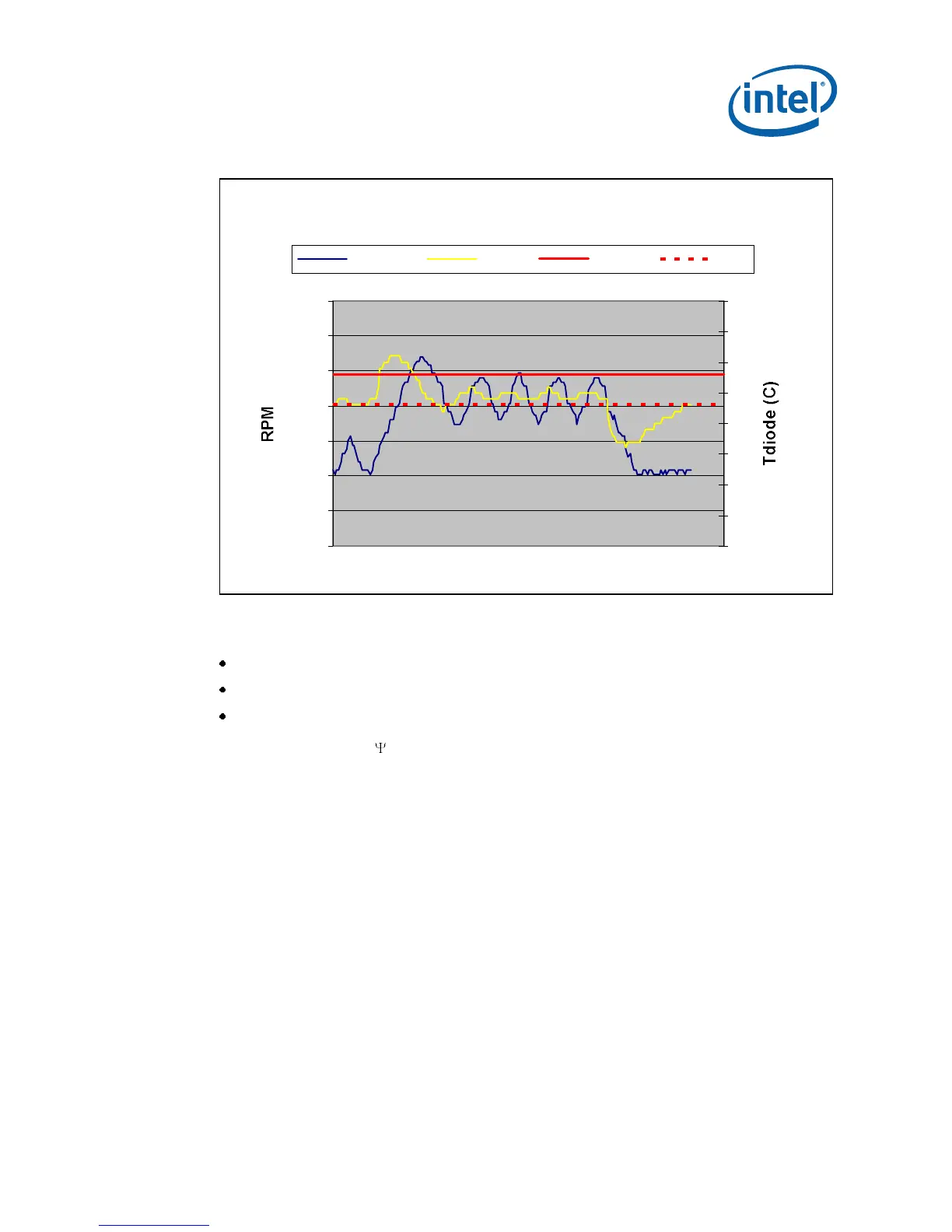
Explains the objective and methodology of the QST algorithm.

7.3 Intel® QST Configuration and Tuning

Describes how to configure and tune the QST subsystem.

Appendix A LGA775 Socket Heatsink Loading

A.1 LGA775 Socket Heatsink Considerations

Discusses heatsink clip load for mechanical and thermal performance.

Appendix D Case Temperature Reference Metrology

D.1 Objective and Scope

Defines the procedure for attaching thermocouples for TC measurement.

D.5 Thermocouple Attach Procedure

Provides a step-by-step guide for attaching thermocouples using solder.

Related product manuals