Case Temperature Reference Metrology
Thermal and Mechanical Design Guidelines 99
18. Place a 3
rd
piece of tape at the end of the step in the groove as shown in
Figure 7-22. This tape will create a solder dam to prevent solder from flowing into
the larger IHS groove section during the melting process.
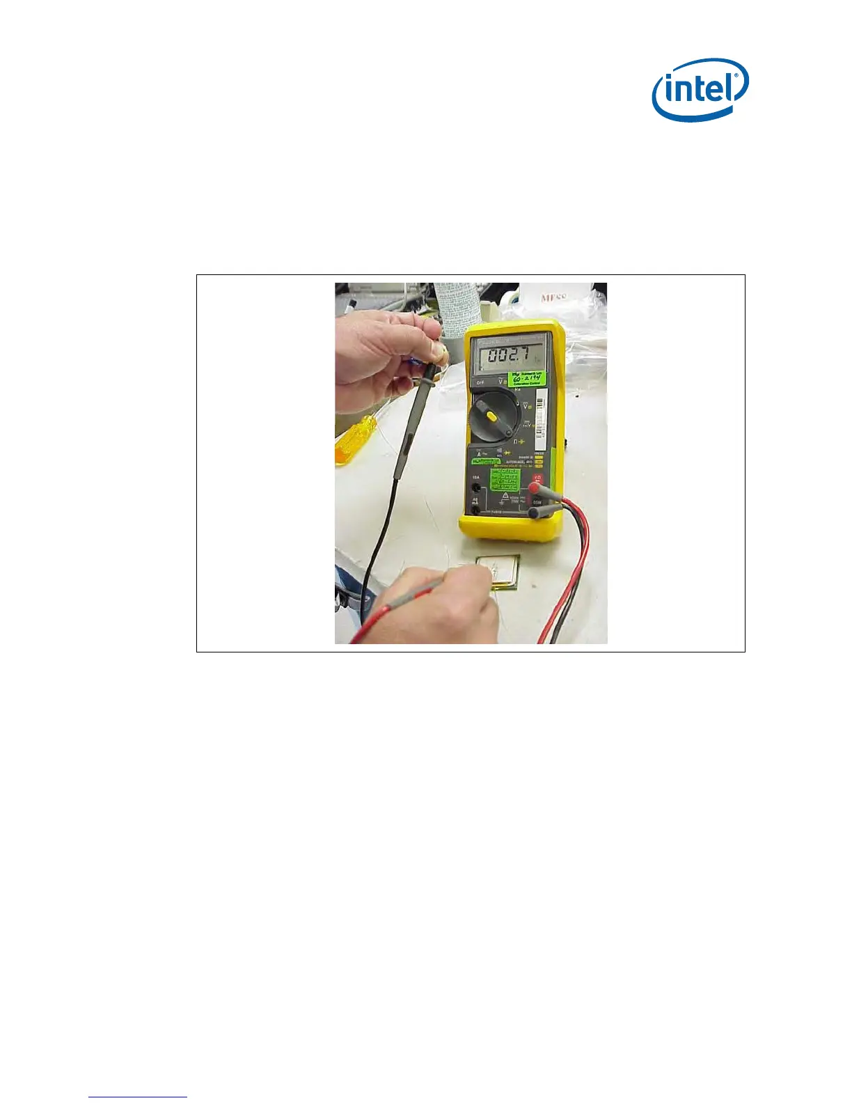
19. Measure resistance from thermocouple end wires (hold both wires to a DMM
probe) to the IHS surface. This should be the same value as measured during the
thermocouple conditioning Section D.5.1.step 3 (Figure 7-23).
Figure 7-23. Measuring Resistance Between Thermocouple and IHS
20. Using a fine point device, place a small amount of flux on the thermocouple bead.
Be careful not to move the thermocouple bead during this step (Figure 7-24).
Ensure the flux remains in the bead area only.
 Loading...