Communication protocol belongs to hexadecimal system. The meaning of message character in
ASCII: “0”…“9”, “A”…”F”, each hex is represented by the ASCII message correspond
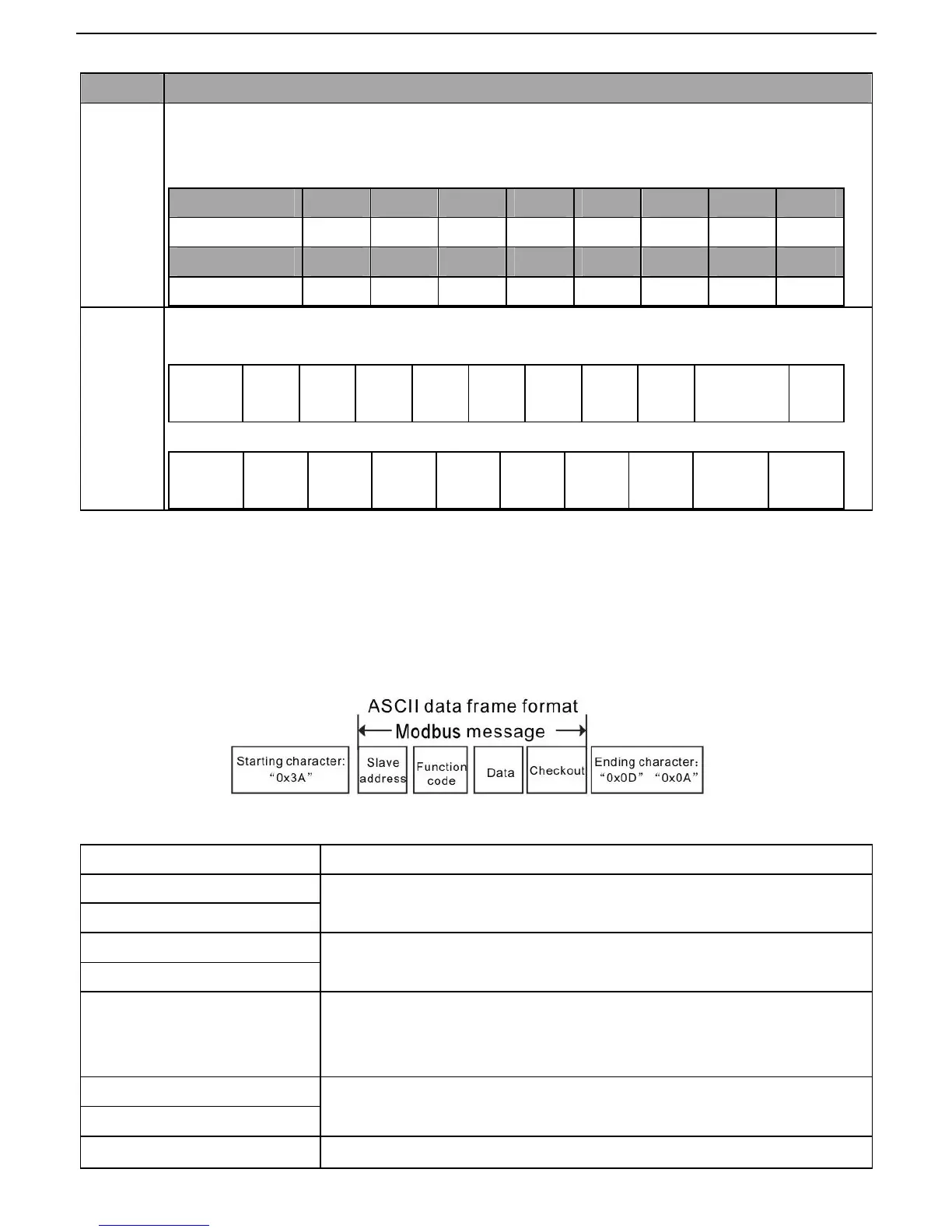
In ASCII mode, the frame header is “:” (“0*3A”), frame end is “CRLF” (“0*0D” “0*0A”) by default. In ASCII
mode, all the data bytes, except for the frame header and frame end, are transmitted in ASCII code mode, in
which four high bit groups will be sent out first and then, four low bit groups will be sent out. In ASCII mode,
the data length is 8 bit. As for ‘A’~‘F’, its capital letters is adopted for ASCII code. The data now adopts LRC
checkout which covers slave address to data information. The checksum equals to the complement of the
character sum of all the participated checkout data.
Standard structure of ASCII frame:
START ‘:’ (0x3A)
Address Hi
Communication address:
8-bit address is formed by the combination of two ASCII codes
Address Lo
Function Hi
Function code:
8-bit address is formed by the combination of two ASCII codes
Function Lo
DATA(N-1)
…
DATA(0)
Data content:
nx8-bit data content is formed by combination of 2n (n≤16) ASCII codes
LRC CHK Hi
LRC check code:
8-bit check code is formed by the combination of two ASCII codes.
LRC CHK Lo
END Hi End character:
 Loading...