107
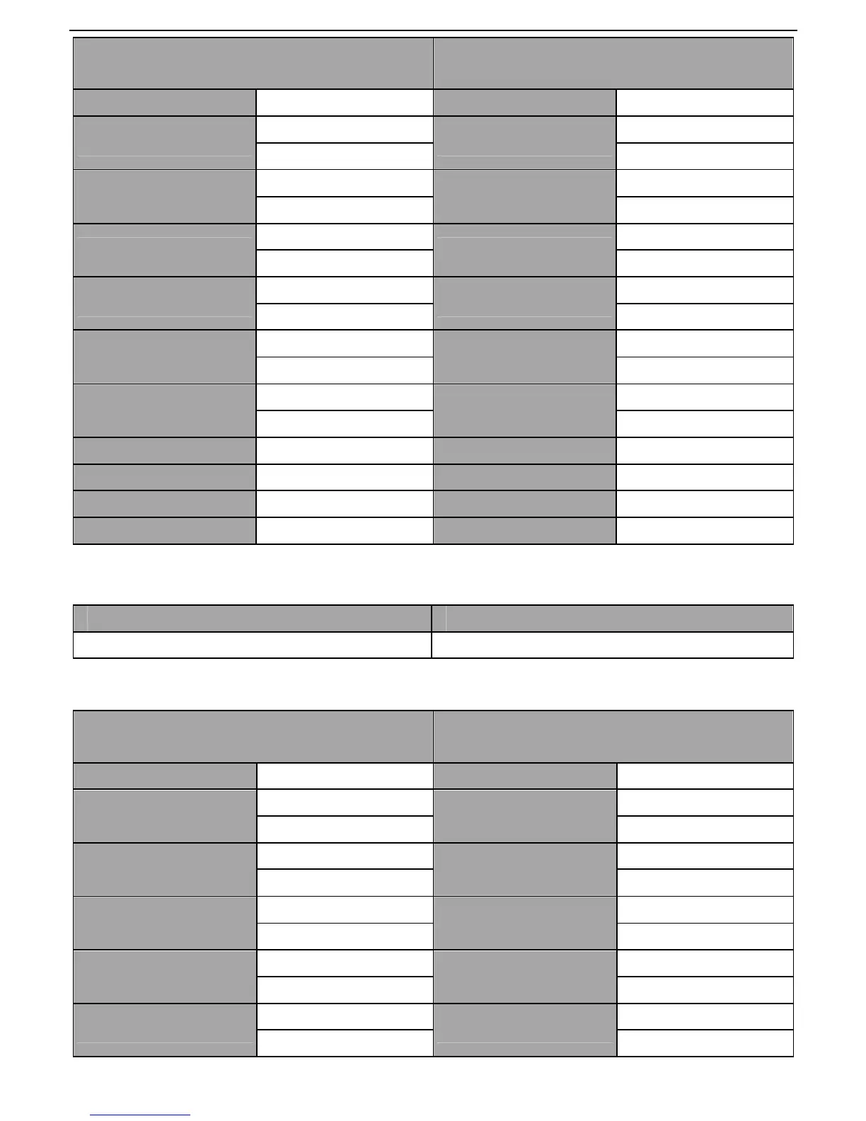
ASCII master command message (the command
sent by the master to the inverter)
ASCII slave response message (the message sent
by the inverter to the master)
START ‘:’ START ‘:’
ADDR
‘0’
ADDR
‘0’
‘2’ ‘2’
CMD
‘0’
CMD
‘0’
‘6’ ‘6’
High bit of write data
‘0’
High bit of write data
‘0’
‘0’ ‘0’
Low bit of write data
‘0’
Low bit of write data
‘0’
‘4’ ‘4’
High bit of data content
‘1’
High bit of data content
‘1’
‘3’ ‘3’
Low bit of data content
‘8’
Low bit of data content
‘8’
‘8’ ‘8’
LRC CHK Hi ‘5’ LRC CHK Hi ‘5’
LRC CHK Lo ‘9’ LRC CHK Lo ‘9’
END Hi CR END Hi CR
END Lo LF END Lo LF
7.3.2.3 Command code: 08H (0000 1000), diagnose function
Meaning of sub function code:
Sub function code Instruction
0000 Return inquiry message data
For instance: carry out circuit detection on drive address 01H, the content of inquiry message word string is
the same with response message word string, its format is listed as below:
ASCII master command message (the command
sent by the master to the inverter)
ASCII slave response message (the message sent
by the inverter to the master)
START ‘:’ START ‘:’
ADDR
‘0’
ADDR
‘0’
‘1’ ‘1’
CMD
‘0’
CMD
‘0’
‘8’ ‘8’
High bit of write data
address
‘0’
High bit of write data
address
‘0’
‘0’ ‘0’
Low bit of write data
address
‘0’
Low bit of write data
address
‘0’
‘0’ ‘0’
High bit of data content
‘1’
High bit of data content
‘1’
‘2’ ‘2’
 Loading...