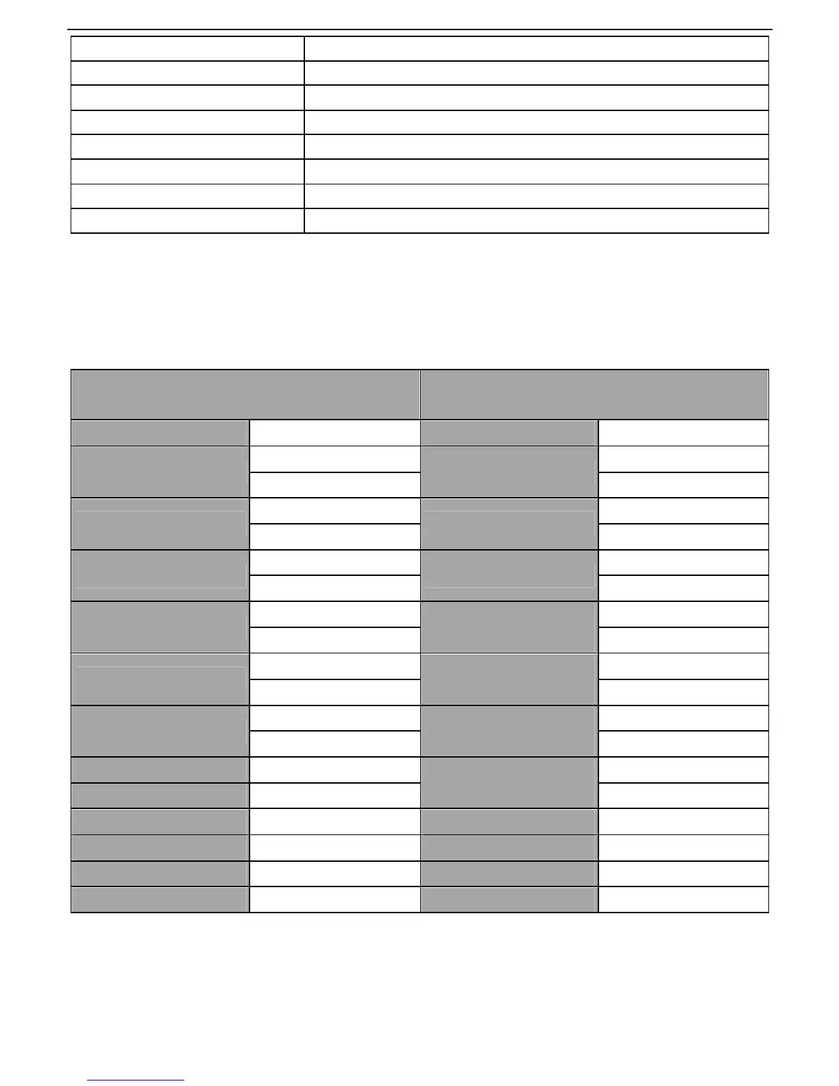
EasyManua.ls Logo

INVT GD20-0R7G-4 User Manual

INVT GD20-0R7G-4
140 pages
To Next Page IconTo Next Page
To Previous Page IconTo Previous Page
Page #107 background imageLoading...
Page #107 background image
Goodrive20 inverters
Communication protocol
106
CMD 10H
High bit of write data
00H
Low bit of write data
04H
High bit of data number
00H
Low bit of data number
02H
Low bit of CRC C5H
High bit of CRC 6EH
END T1-T2-T3-T4 (transmission time of 3.5 bytes)
7.3.2 ASCII mode
7.3.2.1Command code: 03H (0000 0011), read N words (Word) (max. number for
continuous reading is 16 words)
For instance: As for the inverter whose slave address is 01H, the starting address of internal storage is 0004,
read two words continuously, the structure of this frame is listed as below:
ASCII master command message (the command
sent from the master to the inverter
ASCII slave response message (the message sent
from the inverter to the master)
START ‘: START ‘:
ADDR
‘0’
ADDR
‘0’
‘1’ ‘1’
CMD
‘0’
CMD
‘0’
‘3’ ‘3’
High bit of starting address
‘0’
Byte number
‘0’
‘0’ ‘4’
Low bit of starting address
‘0’
High bit of data address
0004H
‘1’
‘4’ ‘3’
High bit of data number
‘0’
Low bit of data address
0004H
‘8’
‘0’ ‘8’
Low bit of data number
‘0’
High bit of data address
0005H
‘0’
‘2’ ‘0’
LRC CHK Hi ‘F’
Low bit of data address
0005H
‘0’
LRC CHK Lo ‘6’ ‘0’
END Hi CR LRC CHK Hi ‘5’
END Lo LF LRC CHK Lo ‘D’
END Hi CR
END Lo LF
7.3.2.2 Command code: 06H (0000 0110), write one word (Word)
For instance: Write 5000 (1388H) to the 0004H address of the inverter whose slave address is 02H, then the
structure of this frame is listed as below:

Table of Contents

Question and Answer IconNeed help?

Do you have a question about the INVT GD20-0R7G-4 and is the answer not in the manual?

INVT GD20-0R7G-4 Specifications

General IconGeneral
ModelGD20-0R7G-4
Enclosure RatingIP20
Output Voltage0-Input Voltage
Control MethodV/F control, sensorless vector control
Overload Capacity150% for 60 seconds
Protection FeaturesOvercurrent, Overvoltage, Undervoltage, Overload, Overheat, Short Circuit, Phase Loss
Communication InterfaceModbus RTU
Rated Power0.75 kW
Input Voltage3-phase 380-480V AC
Input Frequency50/60Hz
Cooling MethodFan cooling

Summary

Safety Precautions

1.1 Safety definition

Defines hazard levels like Danger, Warning, and Note.

1.2 Warning symbols

Explains the meaning of various safety symbols used in the manual.

1.3 Safety guidelines

Provides essential safety rules for operating the inverter.

1.3.1 Delivery and installation

Covers safe practices for handling and installing the inverter.

1.3.2 Commissioning and running

Outlines procedures for starting and operating the inverter safely.

Product Overview

Installation Guidelines

3.1 Mechanical installation

Covers environmental requirements and physical mounting of the inverter.

3.2 Standard wiring

Details the connection diagrams for main and control circuits.

Keypad Operation Procedure

4.1 Keypad introduction

Introduces the inverter's keypad and its functions.

Fault Tracking

6.1 Maintenance intervals

Lists recommended maintenance checks and intervals for the inverter.

6.2 Fault solution

Provides guidance on identifying, troubleshooting, and resolving inverter faults.

Communication Protocol

Appendix A Technical Data

Appendix C Peripheral Options and Parts

Related product manuals