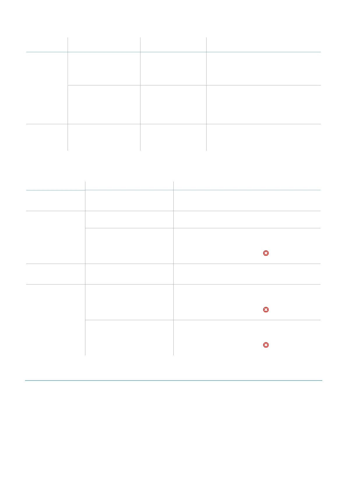
Status
Inxpect Safety
application messages
Problem Remedy
5 flashes *
MASKING, Signal error Masking, micro-
controller, micro-
controller peripherals,
radar or radar control in
error
Check that the sensor is correctly installed
and that the area is free of any objects
that obstruct the field of view of the
sensors.
PERIPHERAL ERROR Error detected by
diagnostics relative to
the internal micro-
controller, its internal
peripherals or
memories
If the issue persists, please contact
assistance service.
6 flashes *
ACCELEROMETERERROR Inclination of the
sensor different from
the installation
inclination
Check if the sensor has been tampered
with or if the side screws or fastening
screws are loose.
Note *: flashes at 200 ms intervals and then with a 2 s pause.
7.1.3 Other problems
Problem Cause Remedy
Undesired alarms Transit of people or objects in
close proximity to the detection
field
Change the sensors sensitivity, "Change the
configuration" on page71.
Machinery in safe
status without
motion in the
detection field
No power supply Check electrical connection.
Contact assistance service if necessary.
Failure of the control unit or one
or more sensors
Check the status of the LEDs on the control unit, see
"Control unit LED" on page73.
Access the application Inxpect Safety, on the
Dashboard page, mouse-over on in
correspondence with the control unit or the sensor.
The voltage value
detected on the SNS
input is zero
The chip that detects inputs is
faulty
Contact assistance service.
The system does not
function correctly
Control unit error Check the status of the LEDs on the control unit, see
"Control unit LED" on page73.
Access the application Inxpect Safety, on the
Dashboard page, mouse-over on in
correspondence with the control unit or the sensor.
Sensor error Check the status of the LEDs on the sensor, see
"Sensor LED" above.
Access the application Inxpect Safety, on the
Dashboard page, mouse-over on in
correspondence with the control unit or the sensor.
7.2 Event log management
7.2.1 Introduction
The event log recorded by the system can be downloaded from the Inxpect Safety application in a PDFfile. The
system saves up to 4500 events, divided in two sections. In each section the events are displayed from the most
recent to the least recent. Above this limit, the oldest events are overwritten.
7.2.2 Download the system log
1. Start the Inxpect Safety application.
2. Click Settings and then Activity History.
7. Maintenance and troubleshooting
LBK System Series| Instruction manual v1.2 SET 2021|SAF-UM-LBKBus-en-v1.2|© 2020-2021 Inxpect SpA
75