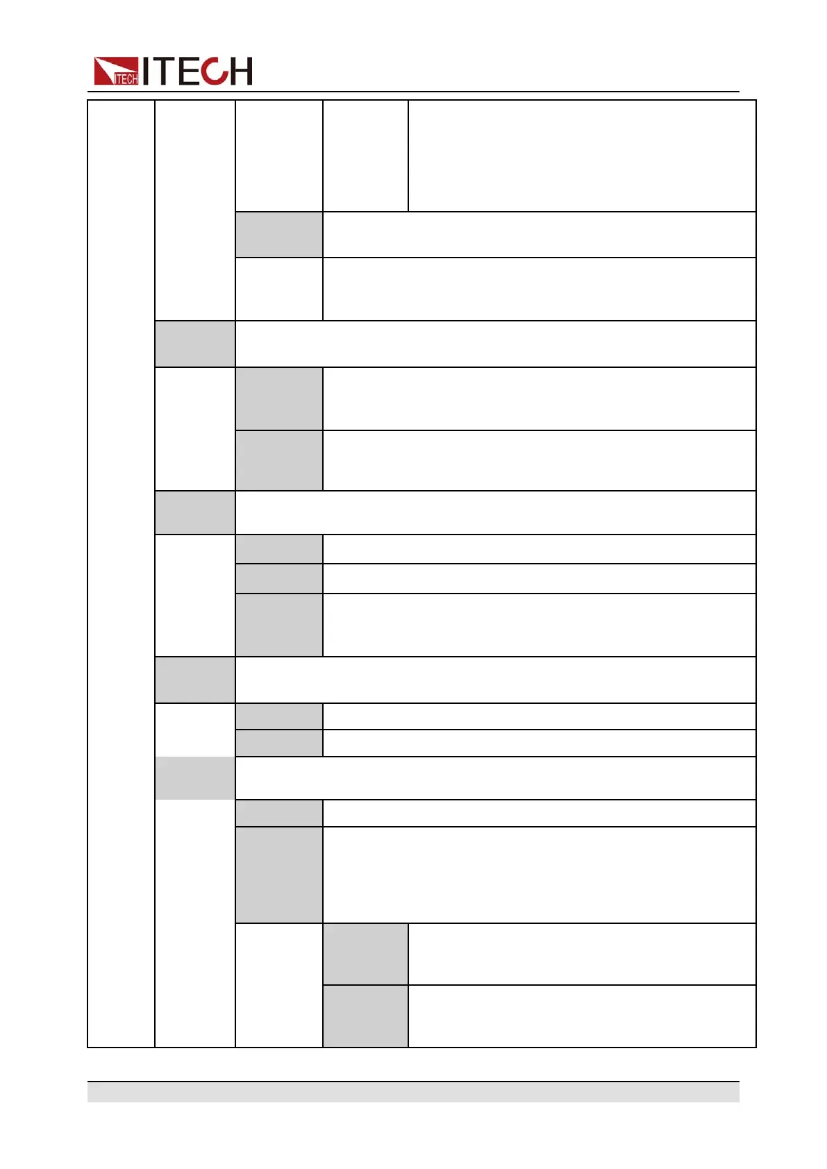
Quick Reference
• Select the baud rate from the following op-
tions: 4800, 9600, 19200, 38400, 57600,
115200
• The data bit, parity bit and stop bit are fixed:
8_None_1
GPIB
When insert IT-E176 communication board into expansion
slot, the menu displays this information.
General purpose interface bus (GPIB) communication
interface.
Set the communication address within the range from 0 to 30.
Trig
Set the rear panel interface TRIG± receiving and transmitting status, and
control the trigger input/output signal of the instrument
Out
When the trigger source is set to Keypad or Bus and the trig-
ger happens, the TRIG± interface generates a high pulse trig-
ger signal.
In
When the trigger source is set to Ext, inputting a high pulse
trigger signal through TRIG± interface can trigger the
instrument
Trig
Source
Set the trigger source
Keypad Keypad trigger, [Shift]+[Esc] (Trigger)
Bus
Remote interface trigger command, like *TRG
Ext
External trigger, when the TRIG± interface state is set to IN
and receive a high pulse signal, the instrument generates
trigger.
Bleeder
Set the Bleeder circuit state (When DUT is the battery, the user need to turn
the Bleeder circuit off)
On Turn the Bleeder circuit on.
Off Turn the Bleeder circuit off.
Inhibit
Port
Set the inhibit output mode of external Inhibit IO.
Off Disables the Inhibit Port function.
Living
Living mode. When the external Inhibit± control terminals input
is in the False state, the output is controlled by the [On/Off]
key on the front panel; when the external Inhibit± control termi-
nals input is in the True state, the output is turned off, and the
output [On/Off] key is invalid at this time .
Nomal
When Inhibit+ and Inhibit– are short-circuited, the
Inhibit± control port input is in the True state, and
if it is not short-circuited, it is in the False state.
Inverted
When Inhibit+ and Inhibit– are short-circuited, the
Inhibit± control port input is in the False state, and
if it is not short-circuited, it is in the True state.
Copyright © Itech Electronic Co., Ltd.
11

 Loading...