EasyManua.ls Logo

ITech IT8200 Series User Manual

ITech IT8200 Series
147 pages
To Next Page IconTo Next Page
To Previous Page IconTo Previous Page
Page #136 background image
Technical Specifications
Copyright ©ITECH Electronic Co., Ltd. 134
3phase
1 ~ 3000
L Range
1phase
1 ~ 2000
uH
reverse phase
3 ~ 2000
3phase
3 ~ 2000
C Range
1phase
0.001 ~ 9900
uF
reverse phase
0.001 ~ 3300
3phase
0.001 ~ 3300
Rc Range
1phase
0.33 ~ 1000
Ω
reverse phase
1 ~ 3000
3phase
1 ~ 3000
RL Range
1phase
0.33 ~ 1000
Ω
reverse phase
1 ~ 3000
3phase
1 ~ 3000
IL Range
1phase
0 ~ 272.7
A
reverse phase
0 ~ 90.90
3phase
0 ~ 90.90
Max peak current
1phase
272.7
A
reverse phase
90.9
3phase
90.9
Circuit Emulation(CE)-Rectifier single phase rlc
R Range
1phase
0.33 ~ 1000
Ω
reverse phase
1 ~ 3000
3phase
1 ~ 3000
L Range
1phase
0.1 ~ 2000
uH
reverse phase
0.3 ~ 2000
3phase
0.3 ~ 2000
C Range
1phase
0.001 ~ 9900
uF
reverse phase
0.001 ~ 3300
3phase
0.001 ~ 3300
R
S
Range
1phase
0 ~ 1000
Ω
reverse phase
0 ~ 3000
3phase
0 ~ 3000
Vcap Range
1phase
0 ~ 499.924
V
reverse phase
0 ~ 499.924
3phase
0 ~ 499.924
Vdiode RangeL
1phase
0 ~ 5
V
reverse phase
0 ~ 5
3phase
0 ~ 5
Max peak current
1phase
272.7
A
reverse phase
90.9
3phase
90.9
Phase Range
Range
Rectified Mode
*6
-82.8º~+82.8º
°
-90º~+90º
Resolution
0.01
°
Accuracy
1% F.S.
°
CF Setting
Range
1.414 ~ 5.0
Resolution
0.001
DC Mode
Voltage Range
30 ~ 499
V
Current Range
1phase
0
990
A
Current Rise time
200
us
work mode
CC, CV, CR, CP
CC+CV
CR+CV
CP+CV
CC+CR
CC+CV+CP+CR
Measurement parameter
Voltage RMS
Range
0
350
Vrms
Resolution
0.01
Accuracy
DC,16Hz
500Hz
0.1%+0.1%
F.S.
Temperature
< 100ppm/
F.S.
Current RMS
Range
0
990
A
Resolution
0.1
A
Accuracy
DC,16Hz
150Hz
0.1% + 0.2%
F.S.
150.01Hz
500Hz
0.2% + 0.3%
F.S.
Temperature
< 200ppm/
F.S.
Peak current
Range
0
2970
A
Resolution
1
Accuracy
0.3% + 0.6%
F.S.
Active power
Range
0
165
kW
Resolution
0.001
kW
Accuracy
0.4% +0.4%
F.S.
Reactive power
Range
0
165
kVAR
Resolution
0.001
kVAR
Accuracy
0.4% +0.4%
F.S.
Apparent power
Range
0
165
KVA
Resolution
0.001
KVA
Accuracy
0.4% +0.4%
F.S.
Range
1
5

Table of Contents

Other manuals for ITech IT8200 Series

Question and Answer IconNeed help?

Do you have a question about the ITech IT8200 Series and is the answer not in the manual?

ITech IT8200 Series Specifications

General IconGeneral
BrandITech
ModelIT8200 Series
CategoryMeasuring Instruments
LanguageEnglish

Summary

Quality Certification and Assurance

Warranty

ITECH's warranty terms for product defects in material and workmanship.

Limitation of Warranty

Conditions that invalidate the product warranty.

Safety Symbols

Safety Precautions

Environmental Conditions

Regulatory Markings

Waste Electrical and Electronic Equipment (WEEE) Directive

Compliance Information

EMC Standard

Standards related to Electromagnetic Compatibility.

Safety Standard

Standards related to product safety.

CHAPTER1 OVERVIEW

1.1 Brief Introduction

Overview of the IT8200 series regenerative AC/DC electronic load.

1.2 Models and Options

Details of available IT8200 series models and their specifications.

1.3 Optional accessories

Information on optional accessories for the IT8200 series.

1.4 Instrument Size Introduction

Guidelines for installing the instrument based on its size.

CHAPTER2 INSTRUMENT INTRODUCTION

2.1 Unpacking and Transportation

Instructions for safely unpacking and transporting the instrument.

2.2 Verifying the Shipment

Procedure to check the contents of the package after shipment.

2.3 Front Panel

Description of the controls and indicators on the front panel.

2.4 Keyboard

Explanation of the functions of the instrument's keyboard.

2.5 Push-on Knob

Details on the operation and function of the push-on knob.

2.6 Rear Panel

Description of the connectors and ports on the rear panel.

CHAPTER3 INSTALLATION

3.1 Connectiong the Power Cord

Steps and precautions for connecting the power cord.

3.2 Connecting Test Lines (Optional)

Guide for connecting test lines for instrument operation.

3.3 Installing Fiber Cables (Only for IT8230-350-180)

Specific instructions for installing fiber optic cables.

Connecting the DUT (Local Measurement)

Connecting the DUT (Remote Sensing)

CHAPTER4 GETTING STARTED

4.1 Power-on the Instrument

Procedure and precautions for powering on the instrument.

4.2 Home-Screen Overview

Explanation of the instrument's main interface and touch screen.

Introduction to Interface Symbols

Explanation of symbols used in the instrument's interface.

4.3 Set load parameters

Guide on configuring load parameters for various tests.

4.4 Input On/Off Control

How to manage the input power to the instrument.

CHAPTER5 OPERATION AND APPLICATION

5.1 Select Phase

How to select single-phase, three-phase, or reverse phase modes.

5.2 Select the Input Mode

Procedure for setting the AC or DC input mode.

5.3 AC Load Function

Description of various AC load modes like CC, CR, CP, CS, CC+CR, CE.

5.4 DC Load Function

Overview of DC load modes including CC, CV, CR, CP, and complex modes.

5.5 Rectified Mode

Explanation of operating the instrument in rectified mode.

5.6 Waveform Selection

How to select different input waveforms.

5.7 C Phase Loss

Simulating C phase loss in three-phase Y connection mode.

5.8 Three-phase unbalance simulation

Configuring three-phase unbalance by disabling balance control.

5.9 Load angle and unload angle control

Setting angle values for loading and unloading.

5.10 Sweep Function

Using the scanning function in CC and CR modes.

5.11 Synchronization Function

Achieving multi-phase power input using digital IO interface.

CHAPTER6 SYSTEM-RELATED FUNCTIONS

6.1 System Menu Reference

Guide to navigating and using the system menu.

6.2 Configuration Menu Reference

Details on setting load input parameters in the config menu.

6.3 Key Lock Function

How to lock and unlock the instrument's keyboard.

6.4 Switching Local/Remote Mode

Procedure for switching between local and remote control modes.

6.5 Save and Recall Operations

Steps for saving and recalling instrument parameter settings.

6.6 Protection Function

Configuring various protection settings like OCP, OPP, OTP.

6.7 Screen Capture Function

How to capture and save the instrument's screen display.

6.8 Trigger Function

Options for trigger sources and modes for oscilloscope function.

6.9 Query the System Log

Accessing and viewing the instrument's system operation log.

6.10 Query the Energy

Using the energy statistics function to view power data.

6.11 Set Parallel Operation Mode

Instructions for connecting multiple instruments in parallel.

6.12 Remote Measurement Function

Setting up local or remote sensing for accurate measurements.

6.13 Digital I/O Function

Configuring digital input/output for logic control and signals.

6.14 Analogue Function (Ext-Program) (Optional)

Using optional analog interfaces for external control.

CHAPTER7 MEASUREMENT FUNCTIONS

7.1 Meter Mode

Using the instrument's basic metering functions.

7.2 Oscilloscope Mode

Displaying and analyzing waveforms with the built-in oscilloscope.

7.3 Harmonic measurement

Measuring and analyzing harmonic parameters in list or bar chart form.

7.4 Recorder Function

Recording and observing input status data over time.

CHAPTER8 CONFIGURATION ARBITRARY WAVEFORM

8.1 List Function

Creating and managing AC waveform sequences using List files.

8.2 Setting of Surge/Sag Configuration

Simulating abnormal voltage fluctuations with surge/sag.

8.3 Self-defined Waveform Function

Customizing and saving input waveform curves.

CHAPTER9 TECHNICAL SPECIFICATIONS

9.1 Main technical parameters

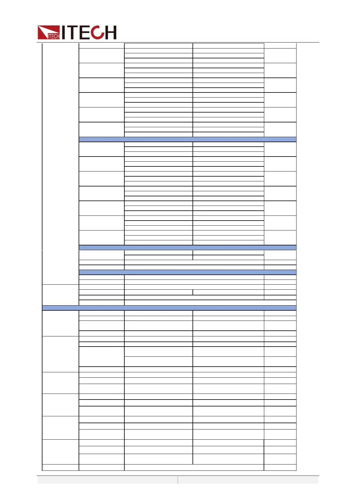
Detailed technical specifications for IT8203-350-30U model.

9.2 Supplemental characteristics

Additional characteristics like calibration frequency and cooling.

CHAPTER10 REMOTE CONTROL

10.1 USB Interface

Connecting and configuring the instrument via USB.

10.2 LAN Interface

Setting up and using the LAN interface for instrument control.

10.3 CAN Interface

Configuring and troubleshooting the CAN communication interface.

10.4 GPIB Interface (Optional)

Details on configuring the optional GPIB interface.

10.5 RS–232 Interface (Optional)

Information on configuring the optional RS-232 interface.

10.6 Commonly Used Commands Overview

Overview of SCPI commands for remote instrument operation.

10.7 Demo Software Introduction

Introduction to the PV8200 demo software for instrument control.

Appendix

Specifications of Red and Black Test Lines

Specifications for optional red and black test lines.