Attachments
Rockbreaker
Rockbreaker
General
WARNING If a second person is involved with the operation ensure that the machine controls are not
operated whilst they are in the working envelope of the machine and attachment, otherwise the other person
could be killed or injured if a control is moved accidentally.
WARNING You or others can be killed or seriously injured if you do unfamiliar operations without first
practising them. Practise away from the worksite on a clear area. Keep other people away. Do not perform
new operations until you are sure you can do them safely.
WARNING The attachment will move when released. Stand clear and to one side when releasing the
attachment.
WARNING The rockbreaker must be positioned correctly before attempting to release it from the quickhitch.
if incorrectly positioned, the rockbreaker could swing or fall suddenly from the machine when releasing the
quickhitch latch hook.
WARNING Always install the quickhitch latch hook locking pin (mechanical only). Failure to install the pin
will result in possible failure of the latching mechanism. Such a failure could result in the sudden release of
an attachment from the machine and you or others could be killed or seriously injured.
To prevent premature wear, failure and breakage, the Quickhitch assembly must be used with a rockbreaker
for short periods only. If the machine is to be used for rock breaking for a long period of time, it is recommended
that the rockbreaker is installed directly on the machine.
When using a rockbreaker, it must be curled towards the machine (as a typical digging operation).
Do not use the rockbreaker as a lever as this causes excessive loads on the locking mechanism.
Installation
1. Set the rockbreaker on solid, level ground. Use safe and correct lifting equipment to move the rockbreaker.
2. Carefully align the holes in the dipper and bucket link with the rockbreaker. If necessary move the machine
to align the pivot pin holes. Refer to Figure 88.
3. Install the pivot pin and lynch pin.
4. Connect the attachment hydraulic hoses to the excavator.
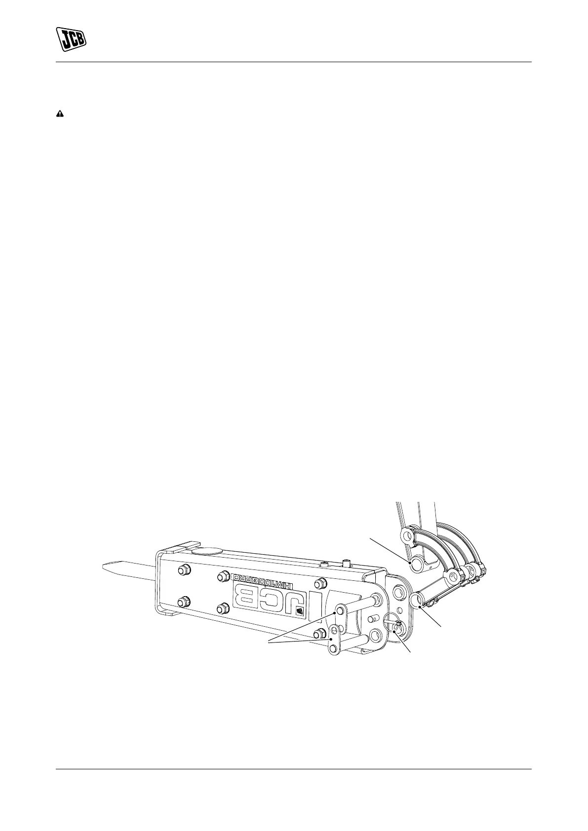
Figure 88.
A Hole (dipper ram) B Hole (bucket link)
C Pivot pins D Lynch pin
Removal
1. When possible, put the attachments on solid, level ground to make the removal procedure safe and easier.
2. Park the machine on the solid, level ground.
98 9831/8250-4 98
JCB © Admin Pimteam - 23/06/2021 05:32.